Interactive 3D WebGL site model
Three.js powered viewport with orbit, pan and zoom. Model a lattice tower, monopole, guyed mast or rooftop pole with configurable height, place transmitters at their mounting heights and azimuths with pointer-based placement, and see the antenna boresights and main-beam lobes drawn in 3D. The colour-coded exclusion-zone heatmap, 3D compliance iso-surfaces, smooth radiation-field shells and a movable vertical cross-section overlay directly on the scene so the spatial extent of the hazard is visible rather than abstract.
ACMA licence import
Search the ACMA radiocommunications register by site name or ID and import the full licensed transmitter set in one click. EIRP, frequency, bandwidth, antenna height, azimuth and polarisation come straight from the register. Antenna patterns are not held in the register, so a generic radiation envelope is inferred per device and clearly labelled. The single best starting point for a real Australian site assessment.
Measured antenna-pattern import
Load measured or OEM patterns from .msi / Planet horizontal-and-vertical files or CSV, and the engine uses the real pattern in preference to the generic 3GPP TR 38.901 envelope. The assessment basis is shown explicitly as Screening (generic), Mixed, or a definitive Measured-pattern assessment, and importing measured patterns reduces the dominant term in the IEC 62232 uncertainty budget.
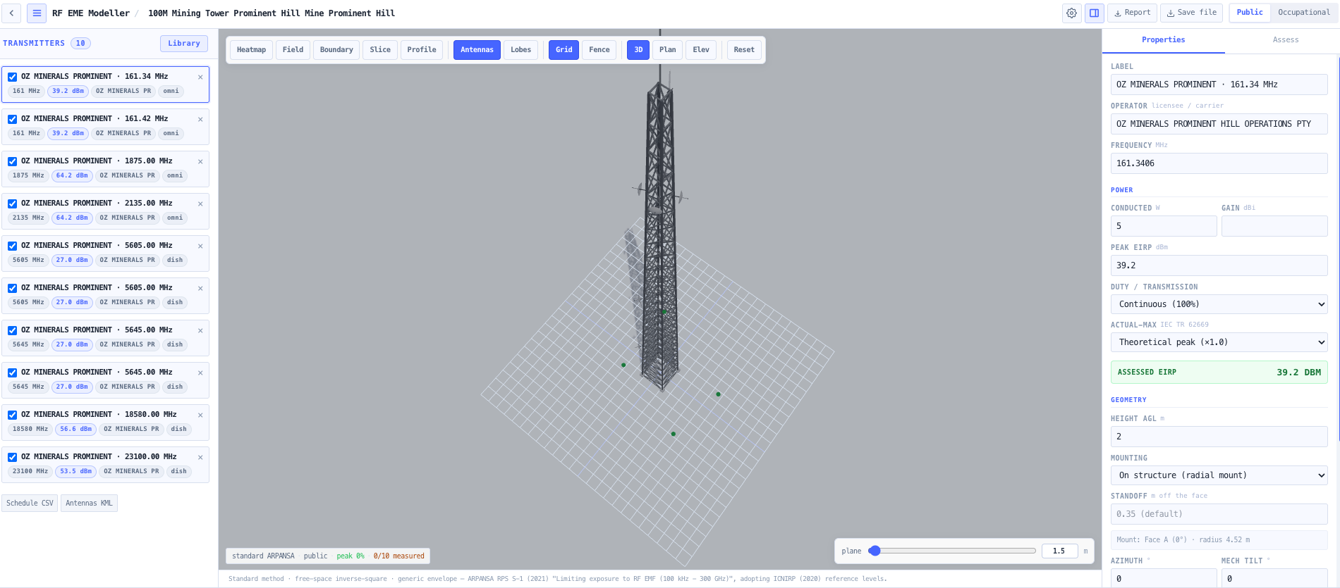
Multi-transmitter summation and IEC TR 62669 power model
Real sites carry many transmitters from several carriers and services. Exposure is summed correctly as Σ(Sᵢ / S_limitᵢ) across all energised transmitters, per the ICNIRP/ARPANSA simultaneous-exposure requirement. Each source is assessed at its time-averaged maximum EIRP (peak EIRP × transmission/duty factor × actual-maximum statistical factor per IEC TR 62669), so 5G beamforming and TDD duty are handled rather than assumed continuous.
ARPANSA / ICNIRP / FCC / IEEE reference levels
Select the standard: ARPANSA RPS S-1 (which adopts the ICNIRP 2020 reference levels), ICNIRP 2020, FCC OET-65 / 47 CFR §1.1310, or IEEE C95.1-2019. Switch between general-public and occupational/controlled populations with standard-correct time averaging. The frequency-dependent reference levels are taken from the validated, unit-tested noIM₃ exposure tables, with the standard citation carried through to the report.
Whole-body spatial averaging and compliance volumes
Assess a point as the spatial peak, or as the IEC 62232 whole-body spatial average over a 2 m vertical line at the receptor (the compliance basis), with the point peak shown as the conservative upper bound. The 100% exclusion boundary is rendered as 3D iso-surfaces for both public and occupational populations, plus a movable horizontal heatmap and a vertical section through any bearing.
Worker climb permit-to-work
Assess a vertical climb up the structure across every face. The engine sweeps bearings around the mast (including each sector azimuth) and reports the worst face, the peak percentage and the height it occurs at. Where the climb exceeds the limit, a route-wide shutdown solver returns the minimal set of sources to de-energise or reduce (in dB) to make the whole climb safe, forcing full isolation where the route passes a live aperture in the near field.
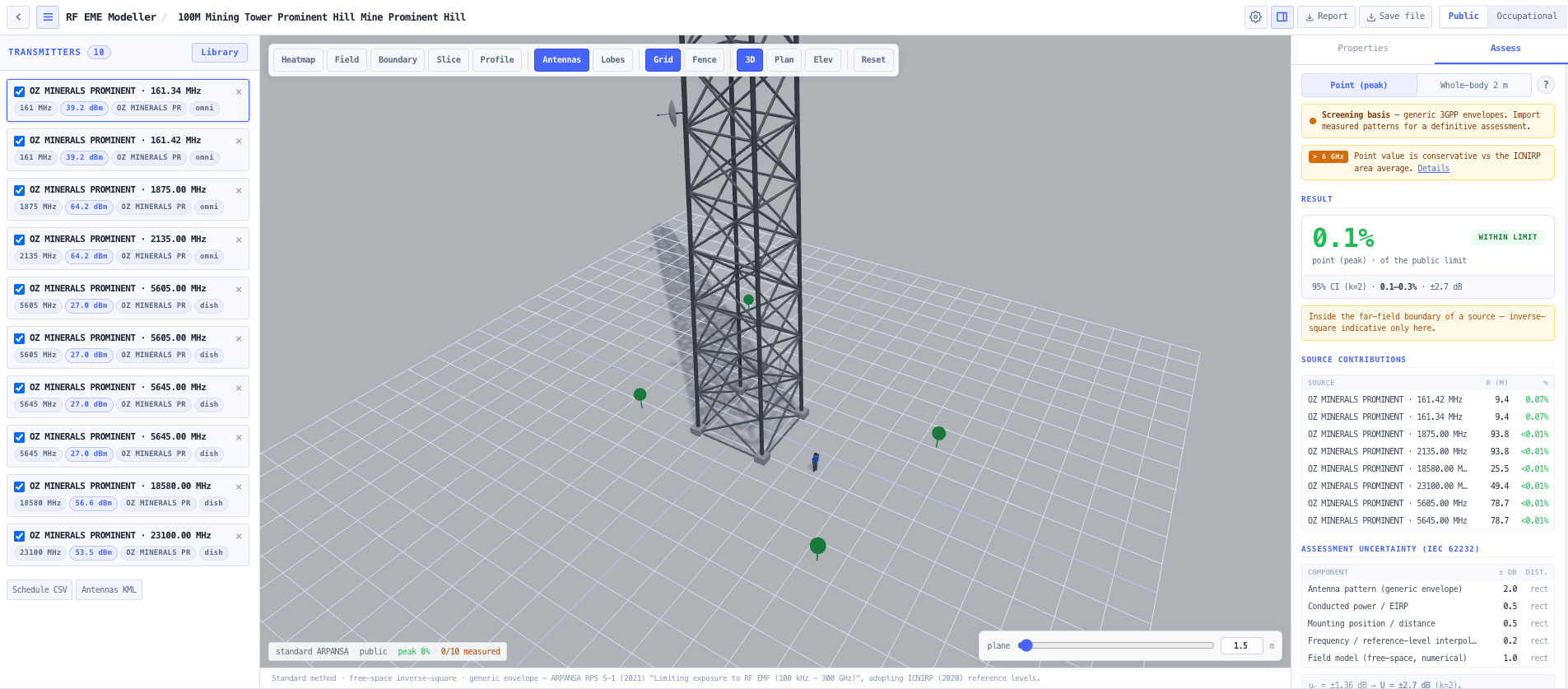
Named receptors and point probes
Define repeatable assessment locations (nearest residence, footpath, balcony, plant deck) as named receptors with a live results table (Σ %, zone, pass/fail) and colour-coded 3D pins, all flowing into the report. Click anywhere to drop an ad-hoc probe for the percentage of the limit, the per-source breakdown, the dominant contributor, a near-field flag and the maximum safe occupational dwell time.
IEC 62232 uncertainty budget
Every result carries a 95% confidence interval. A transparent Type-B uncertainty budget (antenna pattern, EIRP, position, reference-level interpolation, field model) is combined in quadrature per the GUM and expanded by k = 2. The dominant antenna-pattern term shrinks when measured patterns are used, so the budget reflects the actual basis of the assessment rather than a fixed figure.
Propagation refinements, honestly labelled
The conservative free-space inverse-square base can be augmented with a worst-case two-ray ground-reflection allowance, first-order image-method wall reflections, ITU-R P.526 terrain diffraction shielding on probes (real DEM), and a cylindrical near-field continuation inside the far-field boundary. Where a model is not included (full multipath/ray-tracing, urban clutter, the >6 GHz area-averaged metric, induced/contact currents below 110 MHz), that is stated explicitly and the conservatism direction is given.
Reproducibility audit digest
Every assessment carries a tamper-evident SHA-256 audit ID derived from only the result-determining inputs plus the engine method version. The same physical assessment always produces the same ID, and any change that could move a number changes it, so a report can be regenerated and defended (or a discrepancy detected) from the ID alone.
Draw the site by hand
The viewport is an editor, not just a display. Sculpt a custom tower as stacked lattice and pole sections, drag the section boundaries on the model to resize them, add work platforms and guy levels, then hang antennas by dragging them up the tower and around it (snapping onto named faces), or place them free-standing anywhere on the site, including on the roof of a site building beside the tower. Buildings drag into position; a rooftop host building slides under its mast. Everything edited by hand lands in the schedules, drawings and report.
Deliverables a rigger and a fencing contractor can act on
The antenna mounting schedule states each antenna's face or leg, height, azimuth and tilts with the assessed EIRP, as a PDF table, a CSV, and KML placemarks over the real site. The site fence / barrier check gives an adequacy verdict against the public limit with a corner setting-out schedule (east/north and lat/lon), total fence length, CSV/KML export and an indicative signage count. Headline ground-level exclusion distances come from the true Σ = 100% contour of the combined field, so offset antennas and multiple hotspots are bounded correctly.
Co-location apportionment by operator
Shared-site compliance is cumulative, but responsibility is per licensee. Transmitters carry their operator (auto-filled from the ACMA licensee on import), and the assessment apportions the cumulative exposure at the worst publicly-accessible point between operators (equal limit-shares by default, or the site's custom sharing arrangement), with a per-operator within-share verdict and the limit headroom available to a prospective co-locator. Shares are clearly labelled as contractual site policy; the regulatory verdict remains the total at or below 100%.
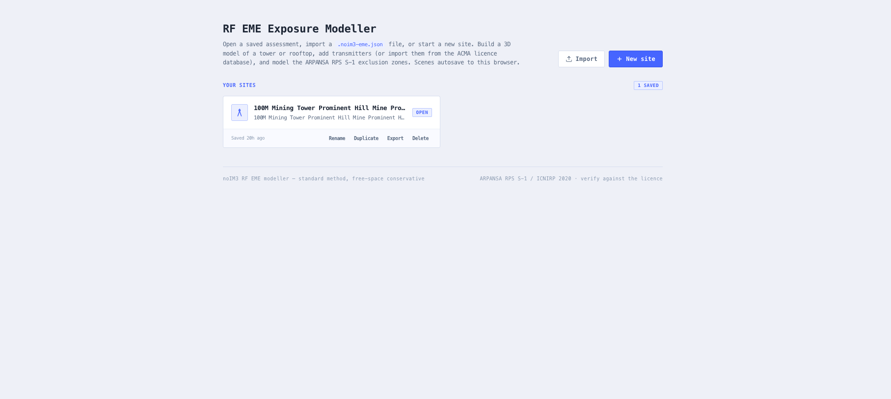
ARPANSA-aligned compliance report
Generate a PDF carrying an ARPANSA-aligned Environmental EME Report (maximum cumulative EME level as a percentage of the public limit at standard distances, 1.5 m AGL), scaled plan and elevation exclusion-zone drawings, the transmitter inventory with assessed EIRP, the access-zone signage schedule, the named-receptor table, the worker climb permit, the uncertainty budget, the audit ID and an explicit methodology and limitations statement. Scenes also export to a portable .noim3-eme.json file and autosave to the browser.