
ACMA Marine Radio and AIS Requirements in Australia: Licences, Qualifications, MMSI and Carriage Rules
Compliance

ACMA Marine Radio and AIS Requirements in Australia: Licences, Qualifications, MMSI and Carriage Rules

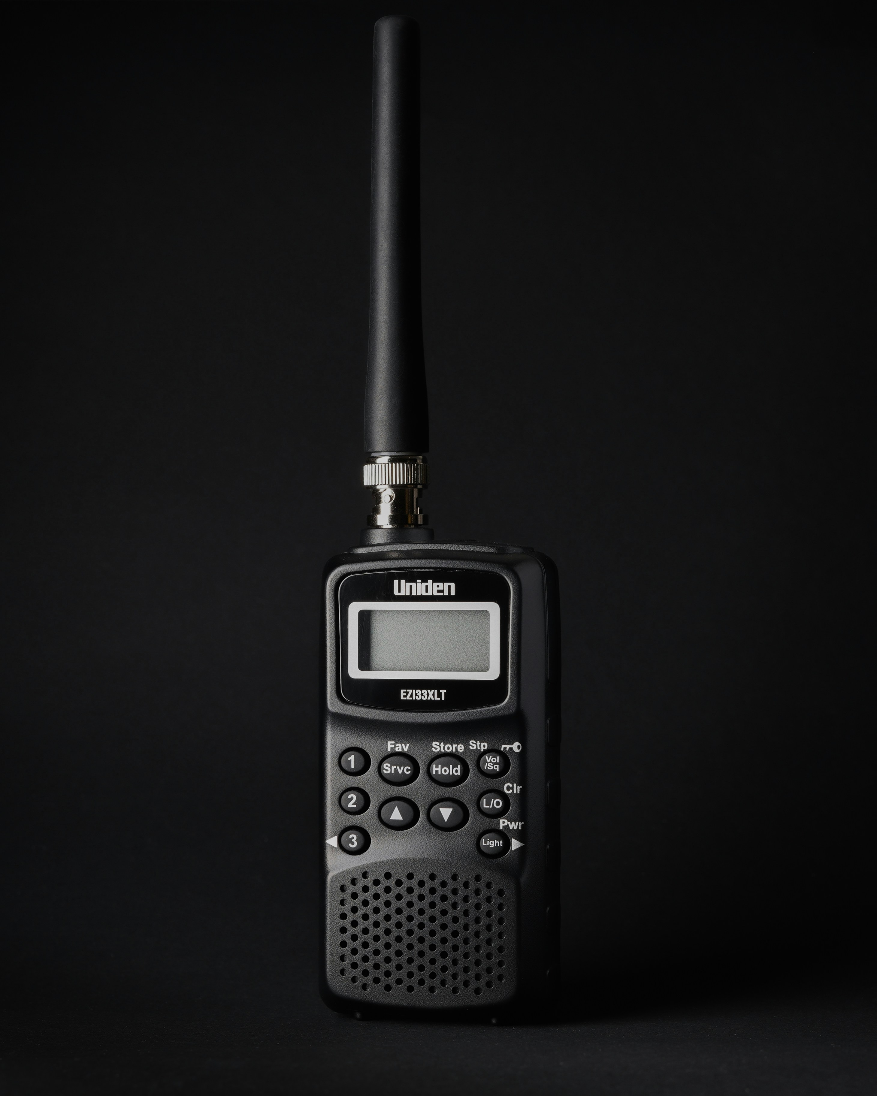
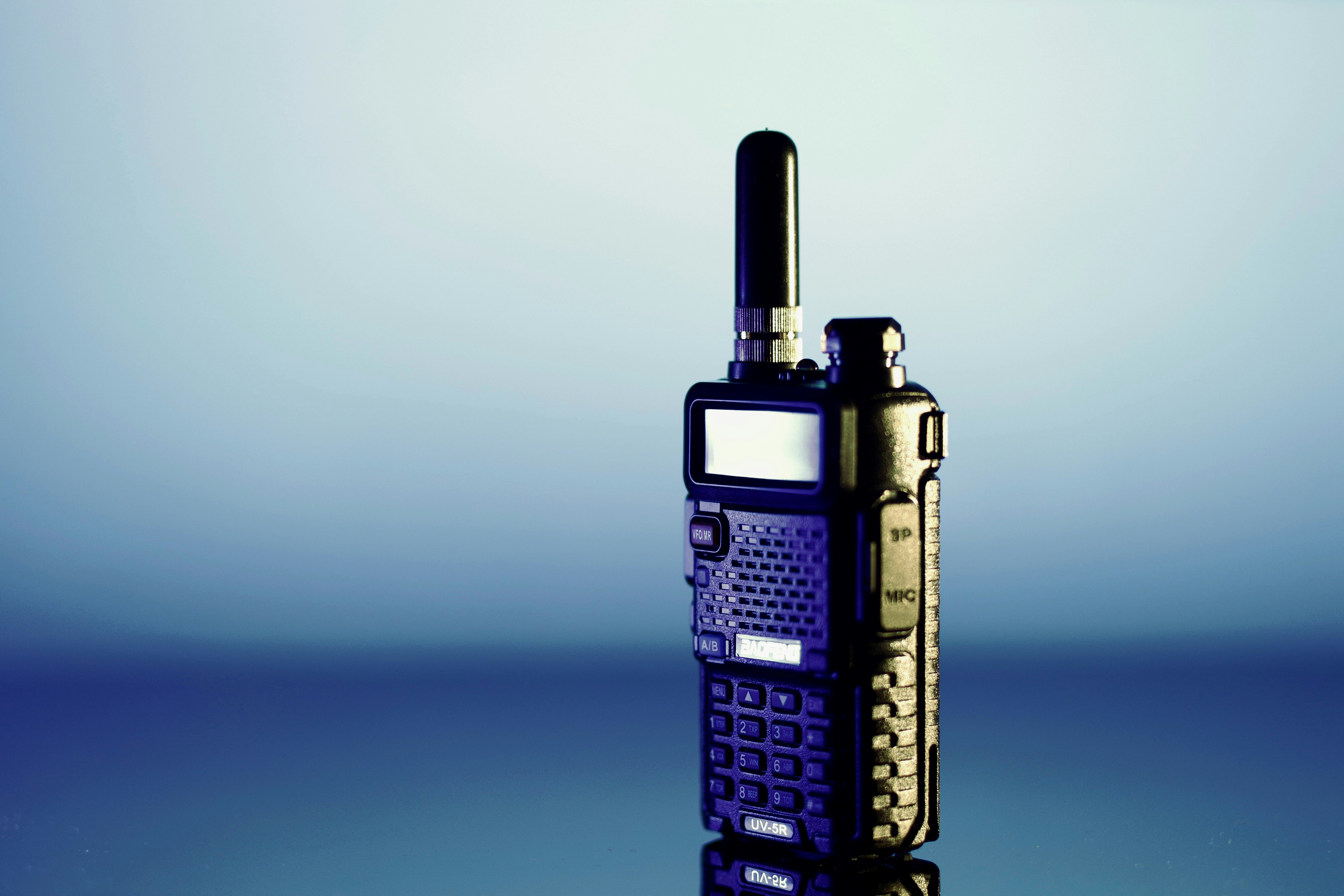
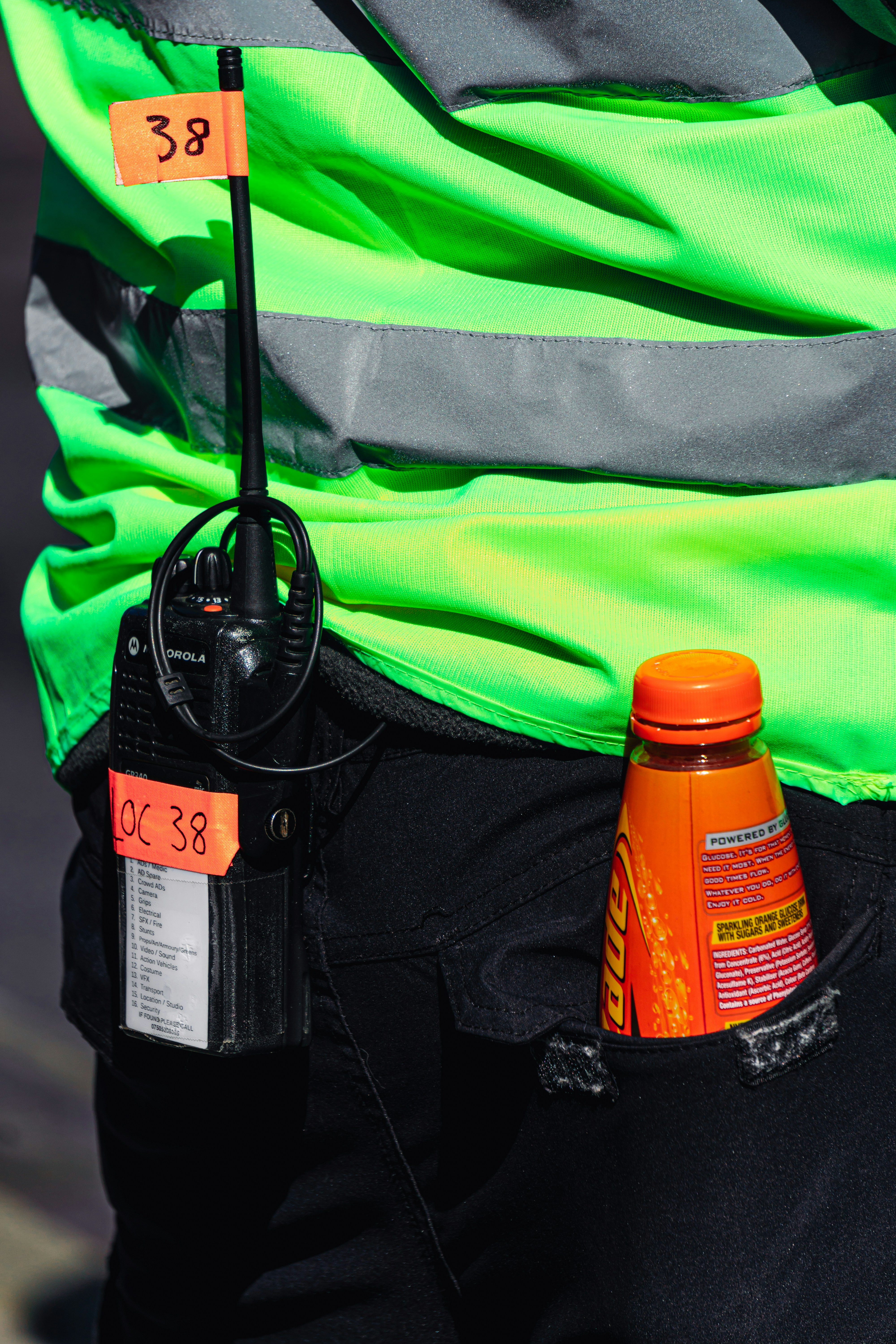
Marine radio in Australia sits under two regulators that answer different questions. The ACMA decides whether you are allowed to transmit at all, and AMSA decides what equipment your vessel has to carry. This guide covers the maritime ship station class licence remade in 2025, when you need an apparatus licence instead, the five operator qualifications and where each one runs out, why an MMSI is compulsory the moment you use DSC or AIS along with the Australian number formats and how the number is programmed in, the exact AIS channels and power limits the ACMA permits, and who is actually required to carry AIS under SOLAS, Marine Order 27, Marine Order 63 and the National Standard for Commercial Vessels.

· 41 min read

ACMA Marine Radio and AIS Requirements in Australia: Licences, Qualifications, MMSI and Carriage Rules

Compliance 41 min
Duplexer, Cavity Filter, Combiner or Multicoupler? What Each One Actually Does
RF Engineering

Duplexer, Cavity Filter, Combiner or Multicoupler? What Each One Actually Does

Four devices sit between a radio and a shared antenna, they look similar in a rack, and buying the wrong one is expensive. This guide explains what each actually does: why filter selection is decided by fractional separation rather than the gap in megahertz, why a duplexer's rejection comes overwhelmingly from a tuned transmission null rather than from its filter skirt, why a hybrid combiner throws away three quarters of your transmit power on four channels while a cavity combiner costs a fraction of a decibel, and why fitting a receive multicoupler can leave a receiver deafer than connecting it straight to the antenna. Includes measured figures from five duplexer legs, catalogue data from 441 real parts, practical selection rules and an FAQ.

· 17 min read

Duplexer, Cavity Filter, Combiner or Multicoupler? What Each One Actually Does

RF Engineering 17 min
P25 vs DMR vs TETRA: Which Digital Radio Standard Should You Actually Choose?
RF Engineering

P25 vs DMR vs TETRA: Which Digital Radio Standard Should You Actually Choose?

On the nominal air interface calculation, P25 Phase 2, DMR Tier III and TETRA all land on one voice path per 6.25 kHz of carrier bandwidth. What actually separates them is how those voice paths land on whole RF carriers, and that decides how many transmitters you combine, how many transmit frequencies you licence, and what the ACMA charges you every year. This guide works the carrier and spectrum maths for each standard, prices the annual licence tax that follows from the choice under a clearly stated duplex access model, explains why a high density site and a remote site favour different technologies, sets out what Australia actually runs and where, and shows why receiver sensitivity figures cannot be compared across the three datasheets.

· 19 min read

P25 vs DMR vs TETRA: Which Digital Radio Standard Should You Actually Choose?

RF Engineering 19 min
How Much Does a Radio Licence Cost in Australia? What the ACMA Actually Charges
Compliance

How Much Does a Radio Licence Cost in Australia? What the ACMA Actually Charges

A single UHF land mobile licence in a high density area carries an annual ACMA tax of $2,062, and the identical licence in a remote area carries $44. That is not a typo, and it is not a discount you apply for. This is a full breakdown of what the ACMA charges for an apparatus licence, worked from the current fee schedule: the difference between the annual tax and the one off administrative charge, why a duplex repeater is charged on two spectrum accesses, the four density areas and what they do to the rate, the five inputs that move the number for a given licence type, and the $940 that an accredited person's frequency assignment certificate saves on a two frequency licence. Includes worked examples, the calculation order that trips people up, and a short FAQ.

· 20 min read

How Much Does a Radio Licence Cost in Australia? What the ACMA Actually Charges

Compliance 20 min
Why Is Ethernet Limited to 100 Metres? Channel, Permanent Link and the 90 Plus 10 Rule
Telecommunications

Why Is Ethernet Limited to 100 Metres? Channel, Permanent Link and the 90 Plus 10 Rule

The 100 metre limit is not a property of Ethernet. It is a property of the cabling standard, and it is a loss budget rather than a distance. This guide explains the 90 metre permanent link and the 10 metres left for cords, why the channel is the thing your electronics actually sees, what really happens past the limit, why 10GBASE-T stops at 37 metres over Category 6, how heat in an Australian roof space shortens a compliant run, and the three limits almost nobody checks. Includes diagrams, the cord length equation and a short FAQ.

· 24 min read

Why Is Ethernet Limited to 100 Metres? Channel, Permanent Link and the 90 Plus 10 Rule

Telecommunications 24 min
How to Choose a Fibre Optic Cable: ADSS, Loose Tube, and Ribbon Explained
Telecommunications

How to Choose a Fibre Optic Cable: ADSS, Loose Tube, and Ribbon Explained

A 72 fibre loose tube cable and a 72 fibre ADSS cable can carry the same glass, yet one is built to be pulled through a duct and the other to hang between poles and carry its own weight in a storm. This guide answers which cable to buy first, then explains the types of fibre optic cable, how ADSS and loose tube differ, when to choose singlemode over multimode, and how aerial span, sag and tension decide an ADSS choice. Includes a decision table, cross section diagrams and a short FAQ.

· 17 min read

How to Choose a Fibre Optic Cable: ADSS, Loose Tube, and Ribbon Explained

Telecommunications 17 min
How Much Antenna Separation Do You Need?
RF Engineering

How Much Antenna Separation Do You Need?

Put two radio systems on one tower and the transmitter on one antenna can deafen the receiver on the next. The real question is not distance but isolation, measured in decibels. This guide opens with a worked rooftop example, then explains the three ways co-located antennas interfere, how to turn a receiver's tolerance into a required isolation figure, and how vertical and horizontal separation deliver it. It uses the ITU-R M.2244 formulas, shows why stacking beats side-by-side spacing, and is clear about where the formulas stop being trustworthy and measurement has to take over.
· 13 min read

How Much Antenna Separation Do You Need?

RF Engineering 13 min
How to Get a Radio Licence in Australia: Apparatus, Spectrum and Class Licences Explained
Compliance

How to Get a Radio Licence in Australia: Apparatus, Spectrum and Class Licences Explained

Getting a radio licence in Australia comes down to one decision made early: which of the three licence types your service belongs to. This guide walks through the process step by step, from checking whether a class licence already covers you, to choosing the right apparatus licence type, to the fork between assigned and non-assigned licences that decides whether you need an accredited person, to coordinating the frequency, lodging the application, and paying the fees. It includes a decision diagram, a worked example, and an FAQ covering UHF radios, cost, licence duration and frequency choice.


· 16 min read

How to Get a Radio Licence in Australia: Apparatus, Spectrum and Class Licences Explained

Compliance 16 min
What Is an ACMA Accredited Person? Frequency Assignment Certificates and What They Can Certify
Compliance

What Is an ACMA Accredited Person? Frequency Assignment Certificates and What They Can Certify

An accredited person is an individual the ACMA has authorised under Part 5.4 of the Radiocommunications Act 1992 to issue certificates that support radiocommunications licensing. There are exactly two kinds of accreditation, and an accredited person does not issue your licence. This guide covers what accreditation is, the difference between a frequency assignment certificate and an interference impact certificate, the legal test a certificate has to satisfy, the obligations that sit behind the signature, and how to check that someone is genuinely accredited.

· 16 min read

What Is an ACMA Accredited Person? Frequency Assignment Certificates and What They Can Certify

Compliance 16 min
What Is Noise Figure? Cascade Noise, the Friis Formula and Where to Put the LNA
RF Engineering

What Is Noise Figure? Cascade Noise, the Friis Formula and Where to Put the LNA

Noise figure is how many decibels of noise a stage adds on top of a perfect receiver, and in a chain those figures do not add. The Friis cascade formula divides every later stage by the gain ahead of it, which is why the first stage sets the system noise figure and why a lossy feeder run in front of the amplifier is the most expensive mistake on the tower. This guide covers noise figure, noise factor and noise temperature, the cascade formula, why passive loss equals noise figure decibel for decibel, a worked four stage chain that gains 2.9 dB purely by moving the LNA, how much gain is enough, the dynamic range you pay for it, Y factor measurement, and when chasing a lower noise figure buys you nothing at all.

· 23 min read

What Is Noise Figure? Cascade Noise, the Friis Formula and Where to Put the LNA

RF Engineering 23 min
What Is a Fibre Optic Loss Budget? How to Calculate Optical Power and Margin
Telecommunications

What Is a Fibre Optic Loss Budget? How to Calculate Optical Power and Margin

A fibre optic loss budget compares the light a transmitter puts into the fibre against the light a receiver needs to see, and asks whether the losses in between leave enough margin. This guide explains optical power in dBm, fibre attenuation by wavelength, connector and splice budgets, transceiver launch power and sensitivity, a worked 12 km site link, receiver overload, PON splitter loss, how much margin to hold for repairs and ageing, and why the link that passes on paper still fails on site.

· 19 min read

What Is a Fibre Optic Loss Budget? How to Calculate Optical Power and Margin

Telecommunications 19 min
What Is Intermodulation (IM3)? Third-Order Products, IP3 and How to Avoid It
RF Engineering

What Is Intermodulation (IM3)? Third-Order Products, IP3 and How to Avoid It

Intermodulation is the interference created when two or more signals mix in a non-linear device and produce new signals at the sums and differences of their frequencies. The third-order products at 2f1 minus f2 and 2f2 minus f1 fall closest to the carriers and are the usual troublemakers. This guide explains active and passive intermodulation, where the products land, the third-order intercept point IP3 and the 3 to 1 rule, a worked multi carrier example, and the filtering, isolation and frequency planning that keep IM off a site.

· 15 min read

What Is Intermodulation (IM3)? Third-Order Products, IP3 and How to Avoid It

RF Engineering 15 min
What Is Erlang? How to Size Channels and Repeaters for Radio Systems
RF Engineering

What Is Erlang? How to Size Channels and Repeaters for Radio Systems

One erlang is one channel kept busy for the whole hour, so traffic in erlangs is simply calls per hour times the average call length in hours. This guide explains what an erlang is, offered versus carried traffic, the busy hour, grade of service, the Erlang B formula for blocking systems, when to use Erlang C or Engset instead, a worked radio fleet example, trunking efficiency, and the N minus 1 check that keeps a critical network on air.

· 14 min read

What Is Erlang? How to Size Channels and Repeaters for Radio Systems

RF Engineering 14 min
What Is Spectral Efficiency? Shannon Capacity, QAM and Real Throughput
RF Engineering

What Is Spectral Efficiency? Shannon Capacity, QAM and Real Throughput

Spectral efficiency is how many bits per second a link squeezes out of each hertz of bandwidth, and it is the number that decides how much data a scarce, licensed slice of spectrum can actually carry. This guide explains what spectral efficiency is, the Shannon-Hartley limit and a worked capacity example, how QAM turns signal to noise ratio into bits per symbol, why higher order modulation demands more SNR, how symbol rate, roll-off and coding set the real throughput, the gap between real links and the Shannon ceiling, and how adaptive modulation and MIMO push more data through the same channel.

· 13 min read

What Is Spectral Efficiency? Shannon Capacity, QAM and Real Throughput

RF Engineering 13 min
What Is Radio Line of Sight? Earth Curvature, K-Factor and the Radio Horizon
RF Engineering

What Is Radio Line of Sight? Earth Curvature, K-Factor and the Radio Horizon

Radio line of sight is not the same as what the eye can see, because the atmosphere bends radio waves back towards the Earth and lets a link reach past the visible horizon. This guide explains what radio line of sight really means, why the effective Earth radius and the k-factor of 4/3 model the bending, the radio horizon formula and the handy 4.12 times root height rule, a worked example for two masts, how the Earth bulge eats into mid-path clearance, why clearing the terrain is still not enough without Fresnel clearance, and how a changing k-factor can quietly break a link that looked fine on paper.

· 13 min read

What Is Radio Line of Sight? Earth Curvature, K-Factor and the Radio Horizon

RF Engineering 13 min
What Is Rain Fade? ITU-R P.838, Rain Zones and Designing for Link Availability
RF Engineering

What Is Rain Fade? ITU-R P.838, Rain Zones and Designing for Link Availability

Rain fade is the extra path loss a radio link suffers when rain falls across it, and above roughly 10 GHz it is the single factor that decides whether a link stays up in a downpour. This guide explains what rain fade is, the ITU-R P.838 specific attenuation formula, how a rain cell is turned into a real hop loss with an effective path length, a worked 20 GHz example, how to scale the loss to a 99.9, 99.99 or 99.999 per cent availability target, what Australian rain zones mean for your fade margin, and the design levers that keep a link closed when the weather turns.

· 13 min read

What Is Rain Fade? ITU-R P.838, Rain Zones and Designing for Link Availability

RF Engineering 13 min
What Is Antenna Gain? dBi vs dBd, Beamwidth and Radiation Patterns Explained
RF Engineering

What Is Antenna Gain? dBi vs dBd, Beamwidth and Radiation Patterns Explained

Antenna gain is the single most misunderstood number on a radio data sheet. It is not amplification, because an antenna adds no power of its own. It is focus, the measure of how tightly a passive antenna concentrates the power it is fed into one direction instead of spreading it everywhere. This guide explains what antenna gain really is, the difference between dBi and dBd and the 2.15 dB that separates them, how gain and beamwidth are two faces of the same trade, how a dish turns physical size and frequency into decibels, how to read a radiation pattern, and where gain sits in a link budget.

· 24 min read

What Is Antenna Gain? dBi vs dBd, Beamwidth and Radiation Patterns Explained

RF Engineering 24 min
What Is NVIS? Near Vertical Incidence Skywave for Regional and Emergency Radio
RF Engineering

What Is NVIS? Near Vertical Incidence Skywave for Regional and Emergency Radio

Near vertical incidence skywave, or NVIS, is a high frequency technique that sends the signal almost straight up so it reflects off the ionosphere and returns over a wide area beneath the antenna, with no skip zone and no need for line of sight. It is how you hold a reliable radio net across rugged or remote country, which makes it central to regional and emergency communication in Australia. This guide explains how NVIS works, the band it uses, why the frequency has to follow the ionosphere up by day and down by night, a worked frequency choice, why the antenna is mounted low, and where it fits for emergency services, mining and pastoral operations.

· 15 min read

What Is NVIS? Near Vertical Incidence Skywave for Regional and Emergency Radio

RF Engineering 15 min
What Is Free Space Path Loss (FSPL)? Formula, Examples and the 6 dB Rule
RF Engineering

What Is Free Space Path Loss (FSPL)? Formula, Examples and the 6 dB Rule

Free space path loss, or FSPL, is the signal a radio link loses simply because the wave spreads out as it travels, before any obstruction, rain or terrain is added. It is the floor of every link budget and the first number a planner reaches for. This guide explains what FSPL is, the formula in every useful form, why it depends on frequency even though empty space absorbs nothing, a worked 5 GHz example, the 6 dB rule for doubling distance or frequency, and where FSPL stops and real world path loss begins.

· 13 min read

What Is Free Space Path Loss (FSPL)? Formula, Examples and the 6 dB Rule

RF Engineering 13 min
What Is Passive Intermodulation (PIM) and How to Prevent It?
RF Engineering

What Is Passive Intermodulation (PIM) and How to Prevent It?

Passive intermodulation, or PIM, is interference a radio system makes for itself when two or more strong transmit signals mix in a passive part that is not perfectly linear, such as a connector, cable joint or antenna. The new signals it creates can fall straight into the receive band and quietly desensitise the receiver. This guide explains what PIM is, the formula for where its products land, a worked cellular example, how it is measured in dBc, what causes it including the rusty bolt effect, and the practical steps that keep it off a site.

· 11 min read

What Is Passive Intermodulation (PIM) and How to Prevent It?

RF Engineering 11 min
What Is Fade Margin and How Much Do You Need?
RF Engineering

What Is Fade Margin and How Much Do You Need?

Fade margin is the number of decibels by which the received signal sits above the receiver's usable threshold, the reserve a radio link holds to ride out multipath, rain and atmospheric fading without dropping out. This guide gives the formula, a worked example, the link between fade margin and availability, why each extra nine of uptime costs about 10 dB in the multipath regime, how rain rewrites the rules above 10 GHz, how much margin Australian paths actually need, and the practical ways to buy more of it.

· 17 min read

What Is Fade Margin and How Much Do You Need?

RF Engineering 17 min
What Is EIRP? EIRP vs ERP and How to Calculate It
RF Engineering

What Is EIRP? EIRP vs ERP and How to Calculate It

EIRP is the power a perfect isotropic antenna would have to radiate to match what your real antenna sends along its main beam. You get it by adding the transmitter power and the antenna gain, then subtracting the feeder loss. Here is the formula, how EIRP differs from ERP, a worked example, and the licence limits and safety distances that all depend on it.

· 7 min read

What Is EIRP? EIRP vs ERP and How to Calculate It

RF Engineering 7 min
What Is the Noise Floor? Thermal Noise, SNR and Receiver Sensitivity Explained
RF Engineering

What Is the Noise Floor? Thermal Noise, SNR and Receiver Sensitivity Explained

The noise floor is the faint thermal noise present in every receiver, the level a wanted signal has to rise above to be decoded. At room temperature it starts at −174 dBm per hertz, then climbs with bandwidth and the receiver noise figure. Add the signal to noise ratio your modulation needs and you have the receiver sensitivity. Here is where −174 dBm/Hz comes from, the noise floor formula with a reference table, how noise figure and SNR fit in, and a worked example that turns into a sensitivity figure.

· 15 min read

What Is the Noise Floor? Thermal Noise, SNR and Receiver Sensitivity Explained

RF Engineering 15 min
How to Calculate an RF Link Budget: A Step by Step Guide with a Worked Example
RF Engineering

How to Calculate an RF Link Budget: A Step by Step Guide with a Worked Example

A link budget adds every gain and subtracts every loss between a transmitter and a receiver to predict the received power, then compares it against the receiver sensitivity to see whether the link will work. Here is the formula, an at a glance budget table, a worked example for a 5.8 GHz point to point link, and the engineering considerations, fade margin, propagation and noise, that decide whether the design survives in service.

· 8 min read

How to Calculate an RF Link Budget: A Step by Step Guide with a Worked Example

RF Engineering 8 min
dBm to Watts, dBi vs dBd and dBc: Every RF Decibel Explained (with Conversion Tables)
RF Engineering

dBm to Watts, dBi vs dBd and dBc: Every RF Decibel Explained (with Conversion Tables)

0 dBm is 1 mW and +30 dBm is 1 watt, so every 10 dB is a tenfold change in power and every 3 dB roughly doubles or halves it. Here is what dB, dBm, dBW, dBi, dBd and dBc each mean, how to convert dBm to watts in both directions, a full conversion table, the dBi to dBd offset, EIRP, and the mistakes that trip people up.

· 14 min read

dBm to Watts, dBi vs dBd and dBc: Every RF Decibel Explained (with Conversion Tables)

RF Engineering 14 min
How Far Do You Need to Stay From a Transmitting Antenna? RF Exposure Safe Distances Explained (ARPANSA RPS S-1 / ICNIRP)
Compliance

How Far Do You Need to Stay From a Transmitting Antenna? RF Exposure Safe Distances Explained (ARPANSA RPS S-1 / ICNIRP)

The safe distance from a transmitting antenna depends on its radiated power, its frequency, and whether the person is a worker or the public. Here is the ARPANSA RPS S-1 and ICNIRP formula, a 900 MHz worked example, a compliance distance chart, and the reasons a single distance is rarely the full answer.

· 8 min read

How Far Do You Need to Stay From a Transmitting Antenna? RF Exposure Safe Distances Explained (ARPANSA RPS S-1 / ICNIRP)

Compliance 8 min
The 900 MHz Band Replan: What Australia's Decision Means for IoT, Mining Radios, and Smart Meter Networks
Spectrum Engineering

The 900 MHz Band Replan: What Australia's Decision Means for IoT, Mining Radios, and Smart Meter Networks

A working engineer's guide to ACMA's 900 MHz replan: the new band edges, what happens to legacy PMR, STL and telemetry users, how LIPD class licensing changes in 915 to 928 MHz, and what LoRaWAN, NB IoT, LTE M and private LTE deployments actually have to recalculate this year.

· 20 min read

The 900 MHz Band Replan: What Australia's Decision Means for IoT, Mining Radios, and Smart Meter Networks

Spectrum Engineering 20 min
Starlink Direct to Cell (D2C) Interference: The Spectrum Coexistence Problem No One Is Planning For
Spectrum Engineering

Starlink Direct to Cell (D2C) Interference: The Spectrum Coexistence Problem No One Is Planning For

Direct to cell (D2C) satellite services are raising the RF noise floor across Australia. If you design fixed links, SCADA, WISP networks or PMR systems, your link budgets may already be outdated. Here is what changes.

· 10 min read

Starlink Direct to Cell (D2C) Interference: The Spectrum Coexistence Problem No One Is Planning For

Spectrum Engineering 10 min