Use Cases · Built on the Platform
See the platform
design something real.
Not a list of calculators, but worked walkthroughs that chain noIM₃ tools in order, from a blank page to a buildable deliverable. Every step opens the tool so you can pick up where the example leaves off.
69
Live tools
End-to-end
Real workflows
AU
Standards & spectrum data
Browser
No install, no licence server
Worked Walkthroughs
From a blank page to a deliverable
Real scenarios across RF, electrical, and fibre. Each one is a chain of tools you run in order. Pick a scenario, then click any step to open the tool and design from there, not from scratch.
Design an underground leaky feeder system
A new decline needs continuous two-way radio coverage end-to-end, with fleet, fixed plant, and emergency channels on one cable. You start with nothing but a length and a channel set. Here is the chain that gets you to a design a contractor can build from.
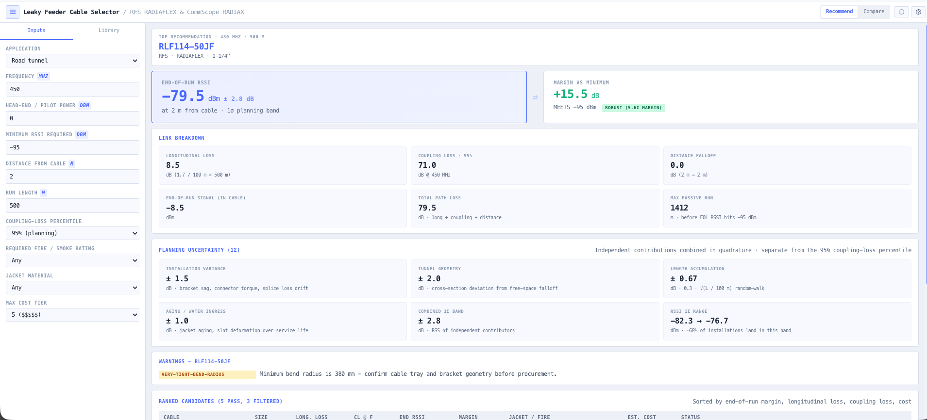
- Leaky Feeder Cable Selector
Pick the radiating cable for your frequency and run length, with coupling and longitudinal loss straight from the vendor specs.
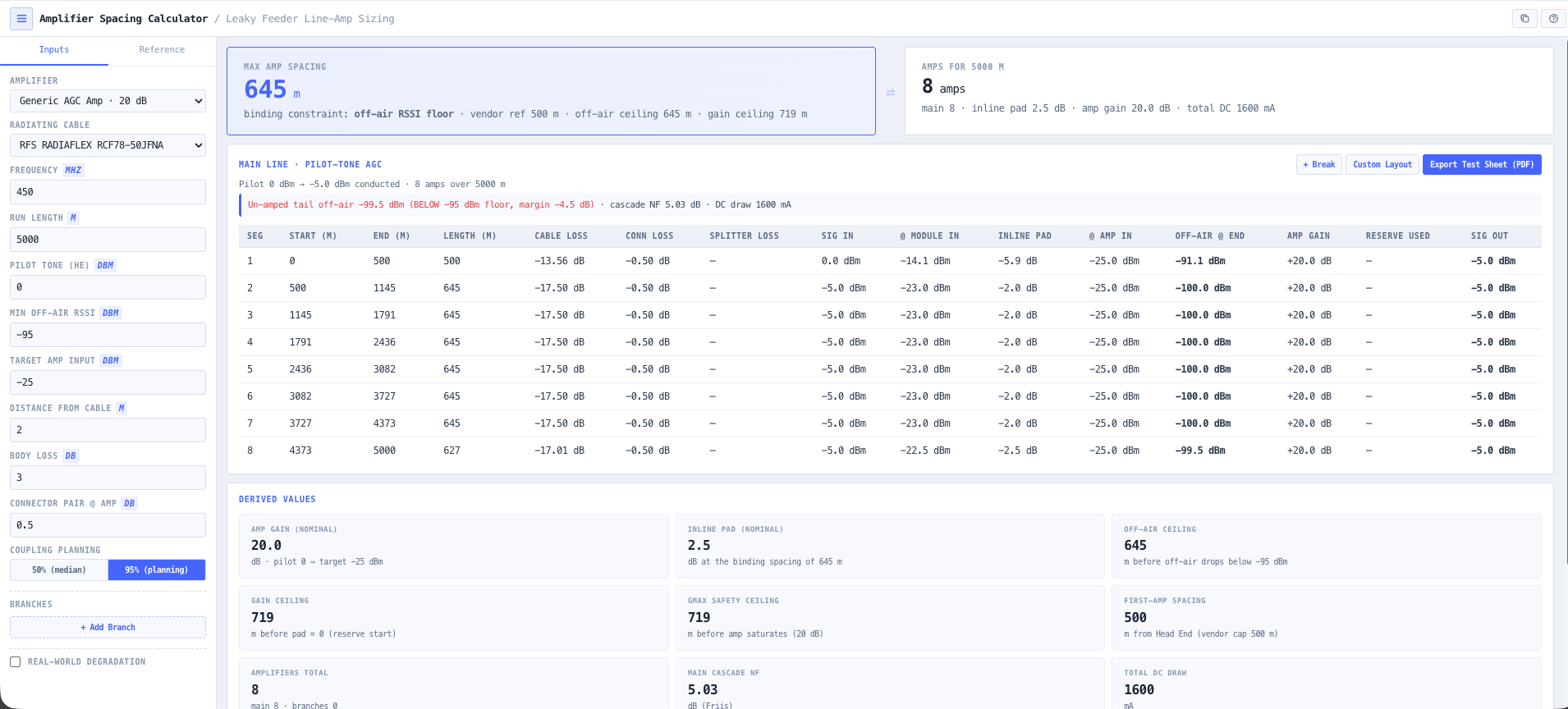
- Amplifier Spacing Calculator
Work out where the line amplifiers sit to hold signal above the coupling threshold, and check the DC voltage drop across the full run.
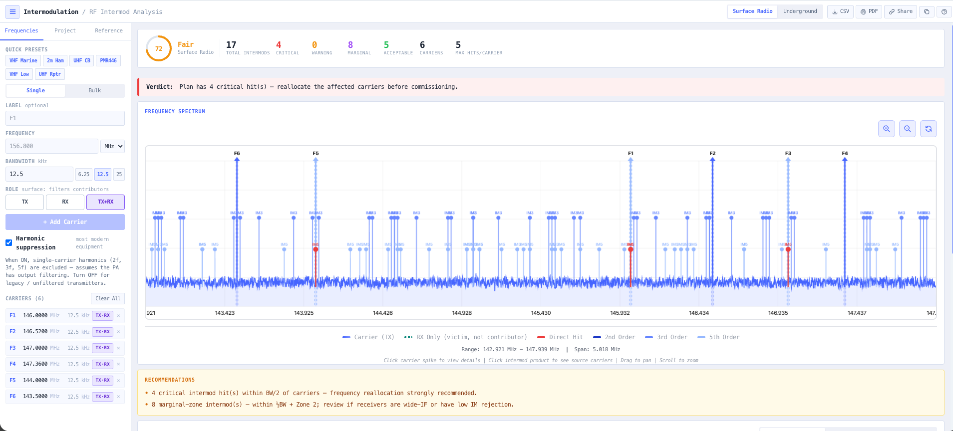
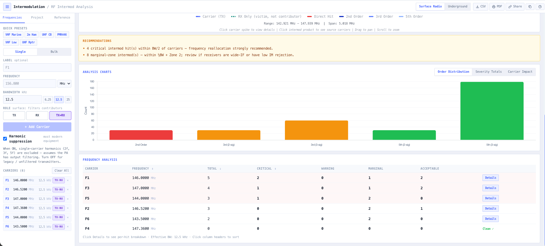
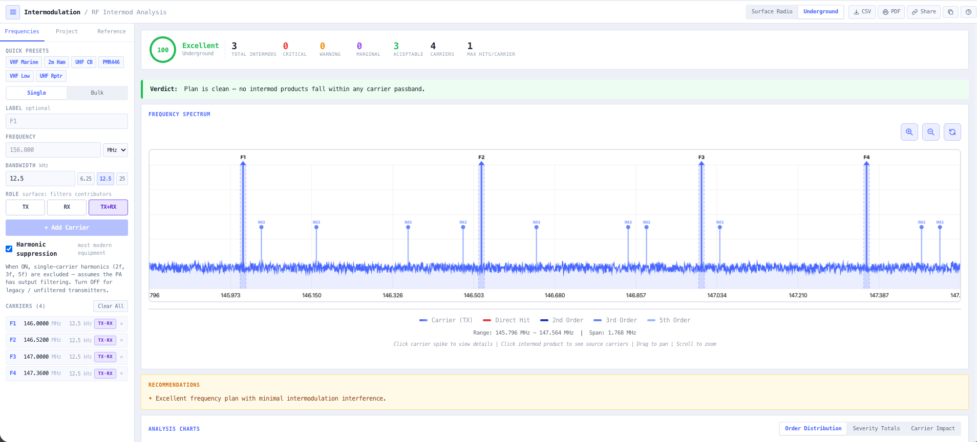
- Intermodulation Calculator
Run 3rd and 5th order products across the proposed channel set so the plan does not bite you the day after commissioning.
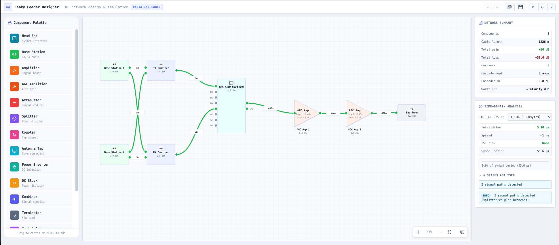
- Leaky Feeder Designer
Lay the head end, cable runs, splitters, and amplifiers on the network canvas and watch the level budget resolve down the line.
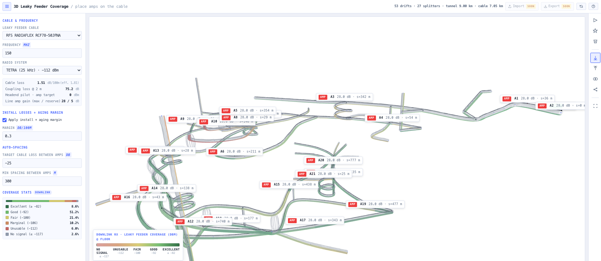
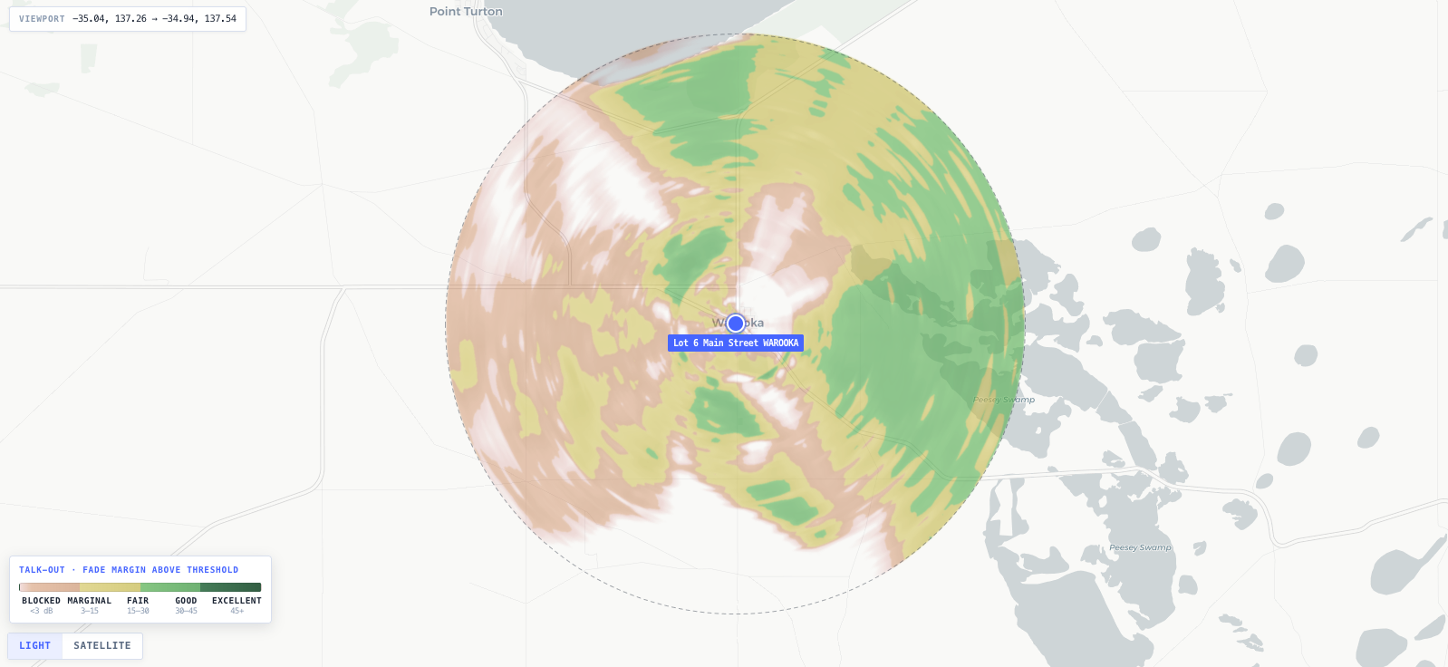
- 3D Leaky Feeder Coverage
See predicted coverage along the heading before any cable is pulled, so the holes show up on screen instead of on shift.
What this gets you
- Coverage holes show up on screen, not on shift
- An intermod-clean channel set that survives commissioning
- A design a contractor can build straight from, DC budget proven
You walk away with: A level balanced leaky feeder design with cable selection, amplifier spacing, a DC budget, an intermod-clean channel set, and predicted coverage along the heading.
Engineer a microwave backhaul link
Two sites, one link, a hard availability target. The link lives or dies on path clearance and fade margin. This chain takes you from the terrain profile to a fade margin you can defend at coordination.
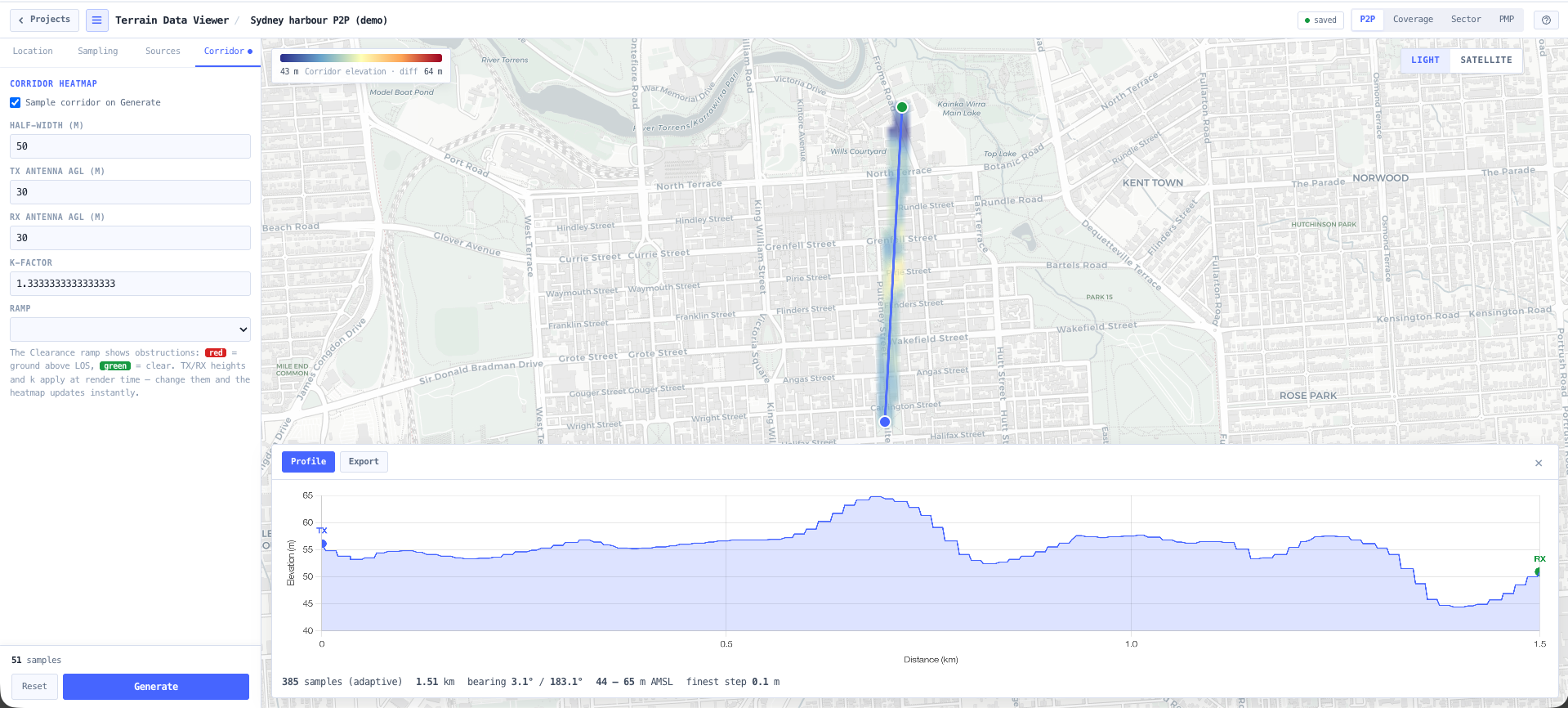
- Terrain Data Viewer
Pull the elevation profile between the two sites from real terrain data and see exactly what sits in the path.
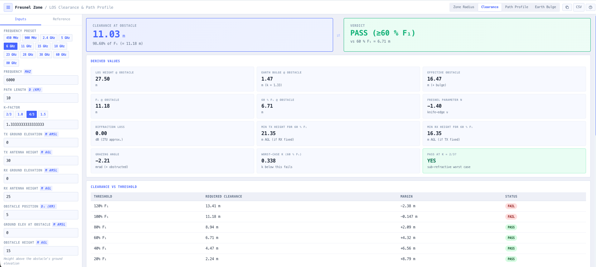
- Fresnel Zone Calculator
Confirm first zone clearance over every obstruction and work out the antenna heights you actually need.
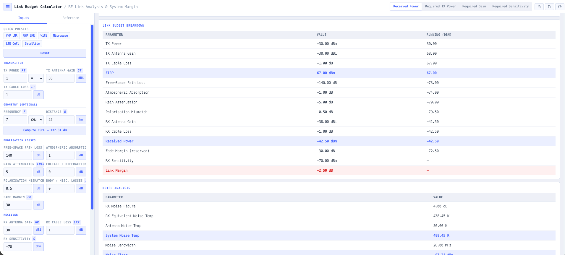
- Link Budget Calculator
Size the radios and antennas. Transmit power, gains, losses, and received level against threshold.
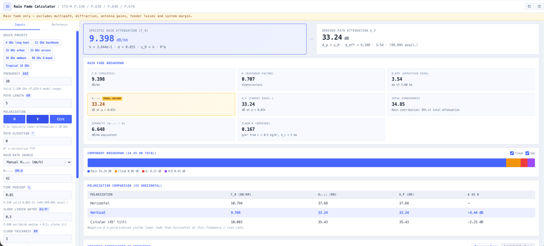
- Rain Fade Calculator
Compute rain attenuation for your region and turn the link budget into an availability figure you can stand behind.
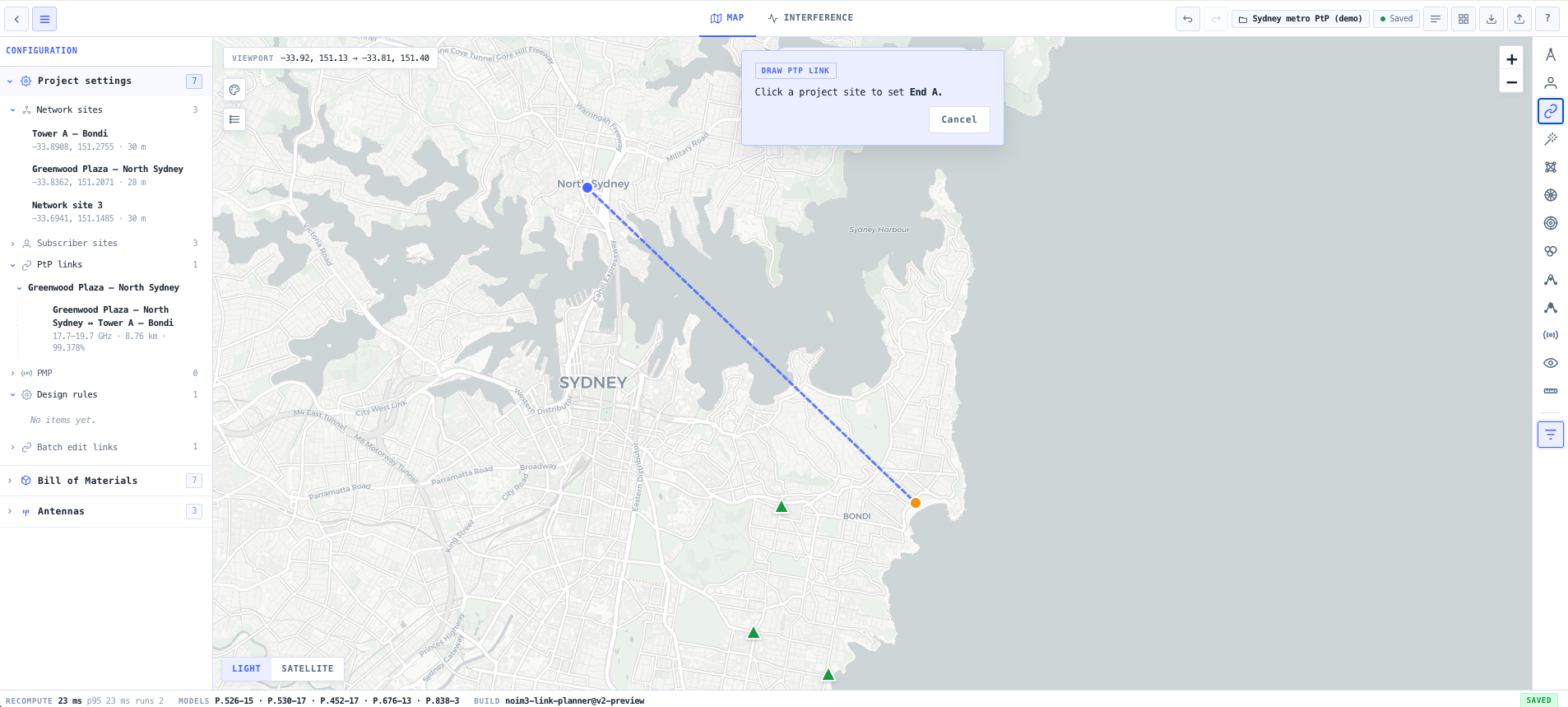
- Link Planner
Bring it together on the map. Place the sites, draw the link, and check it against the ACMA registered services nearby.
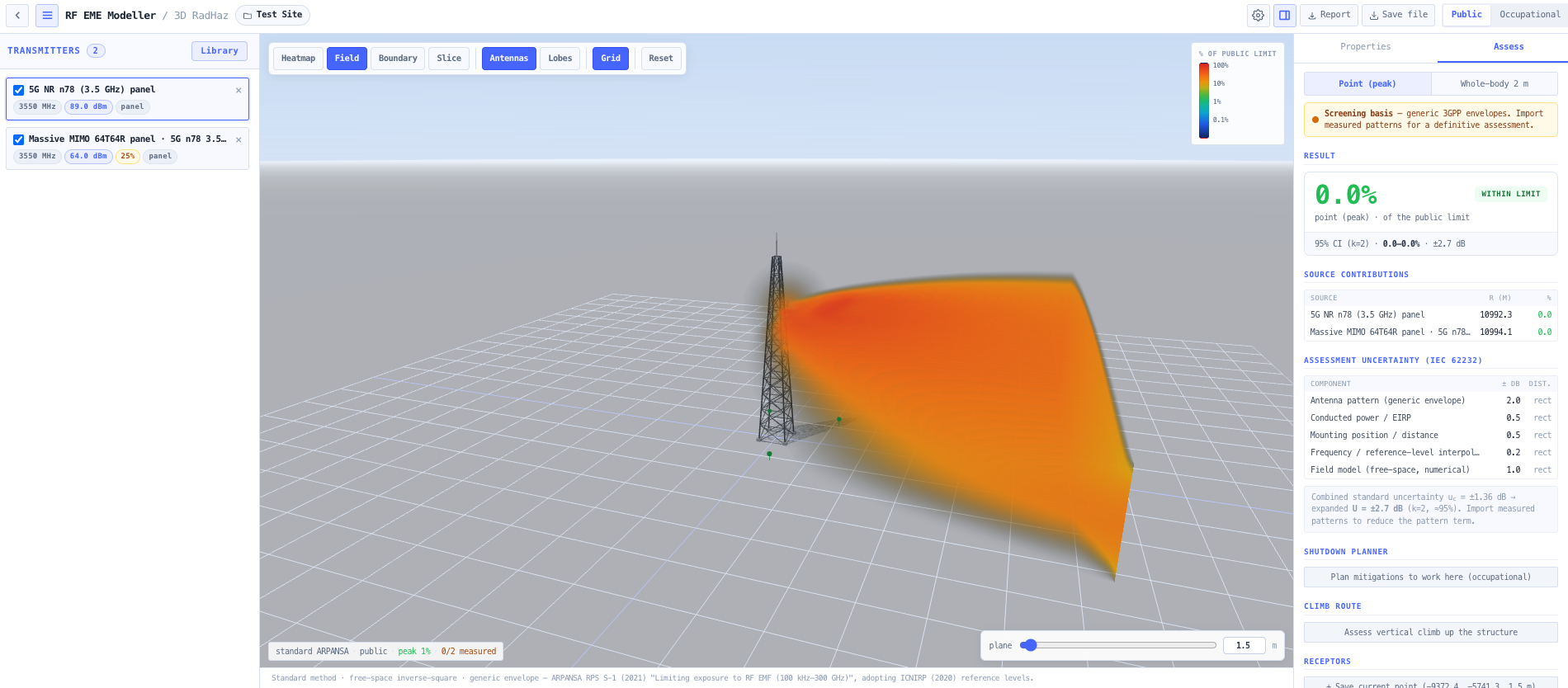
- RF EME Exposure Modeller
Model the RF exposure around the dish and produce the exclusion zones and ARPANSA compliance report for the site.
What this gets you
- A fade margin you can defend at coordination
- Antenna heights and equipment sizing fixed before procurement
- The ARPANSA exposure report done up front, not retrofitted
You walk away with: A cleared and budgeted point-to-point link with antenna heights, equipment sizing, a rain fade availability figure, a coordination view, and an RF exposure compliance report ready for procurement.
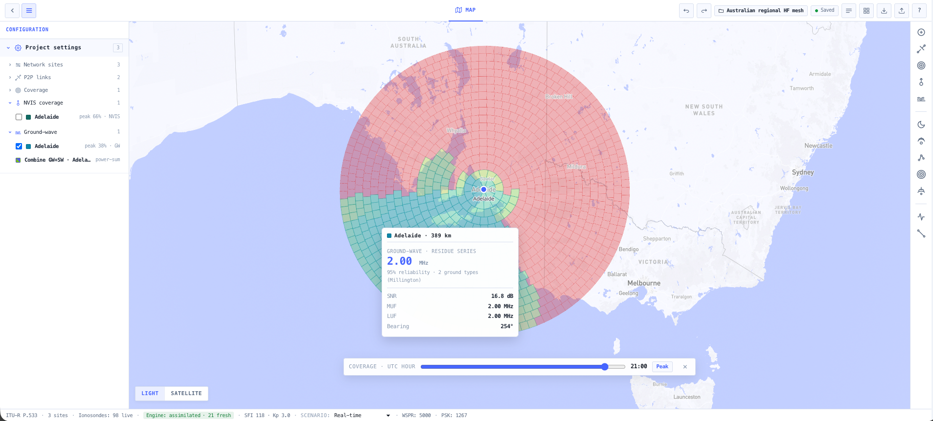
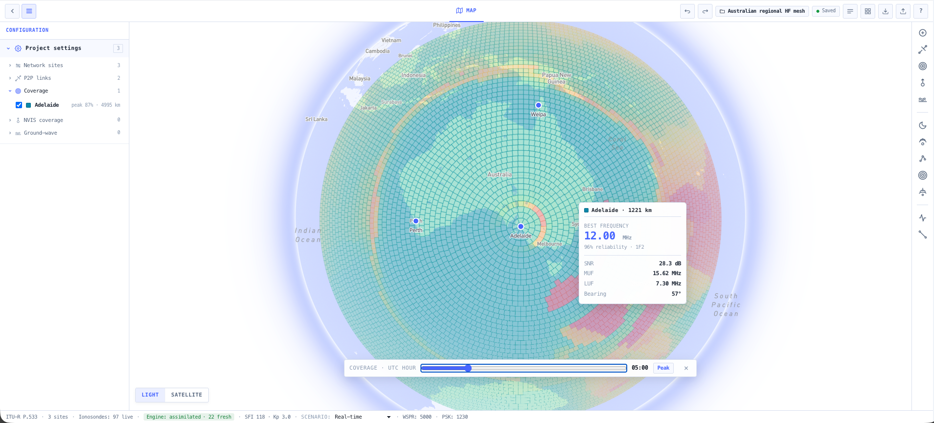
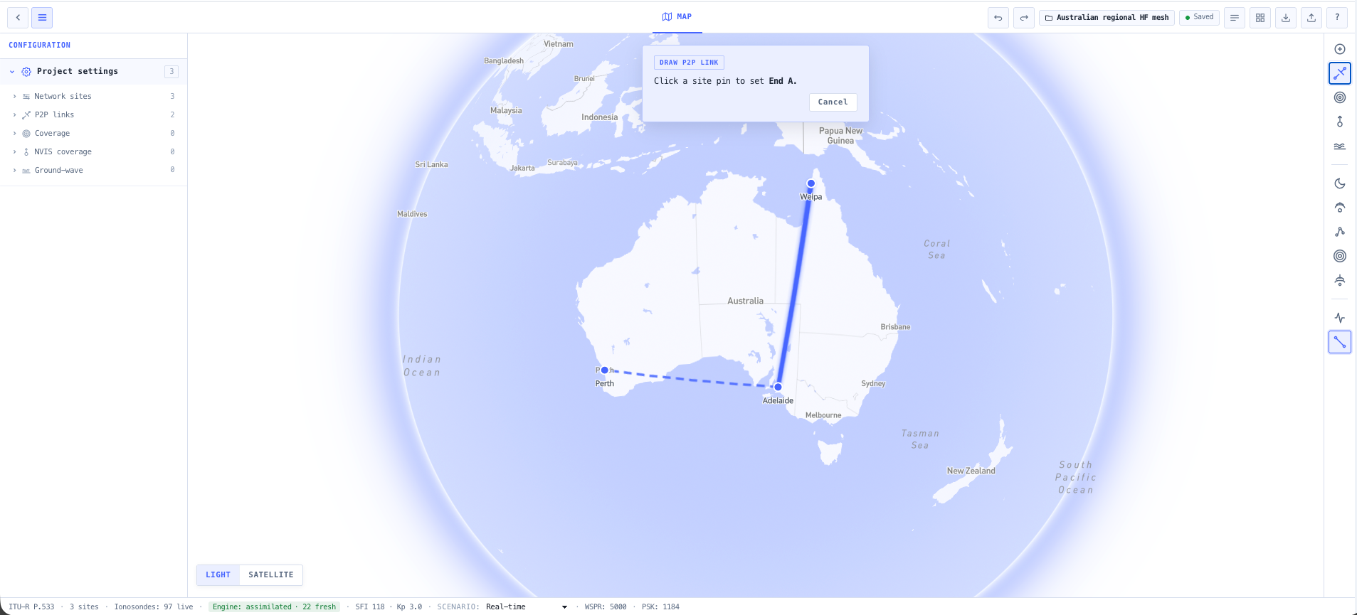
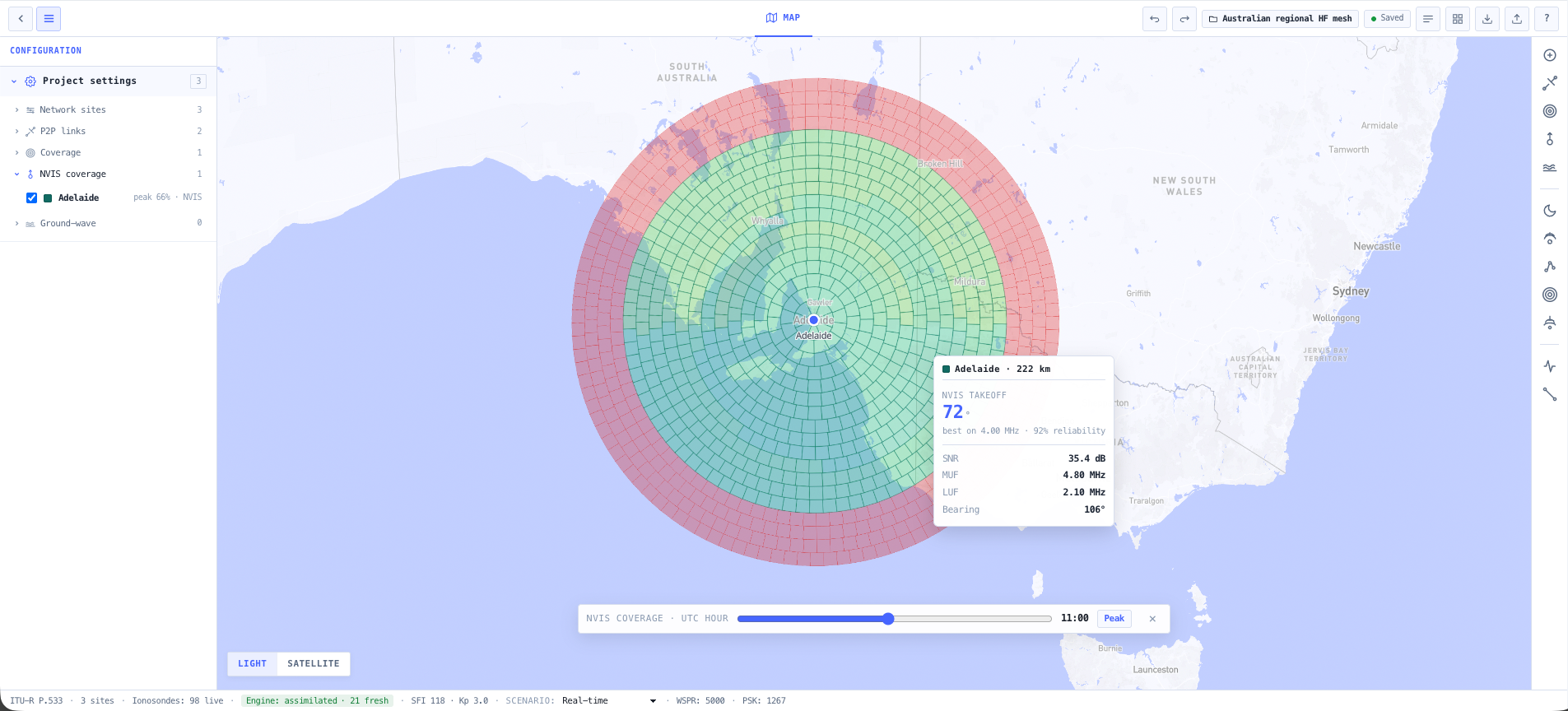
Plan an HF network for remote operations
A remote operation needs to talk across hundreds of kilometres, day and night, with no cellular and no satellite to fall back on. HF works only if the frequency plan tracks the ionosphere. This chain builds that plan.
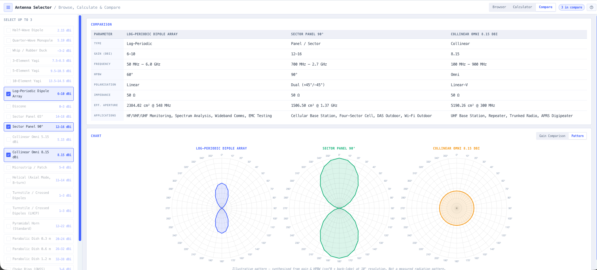
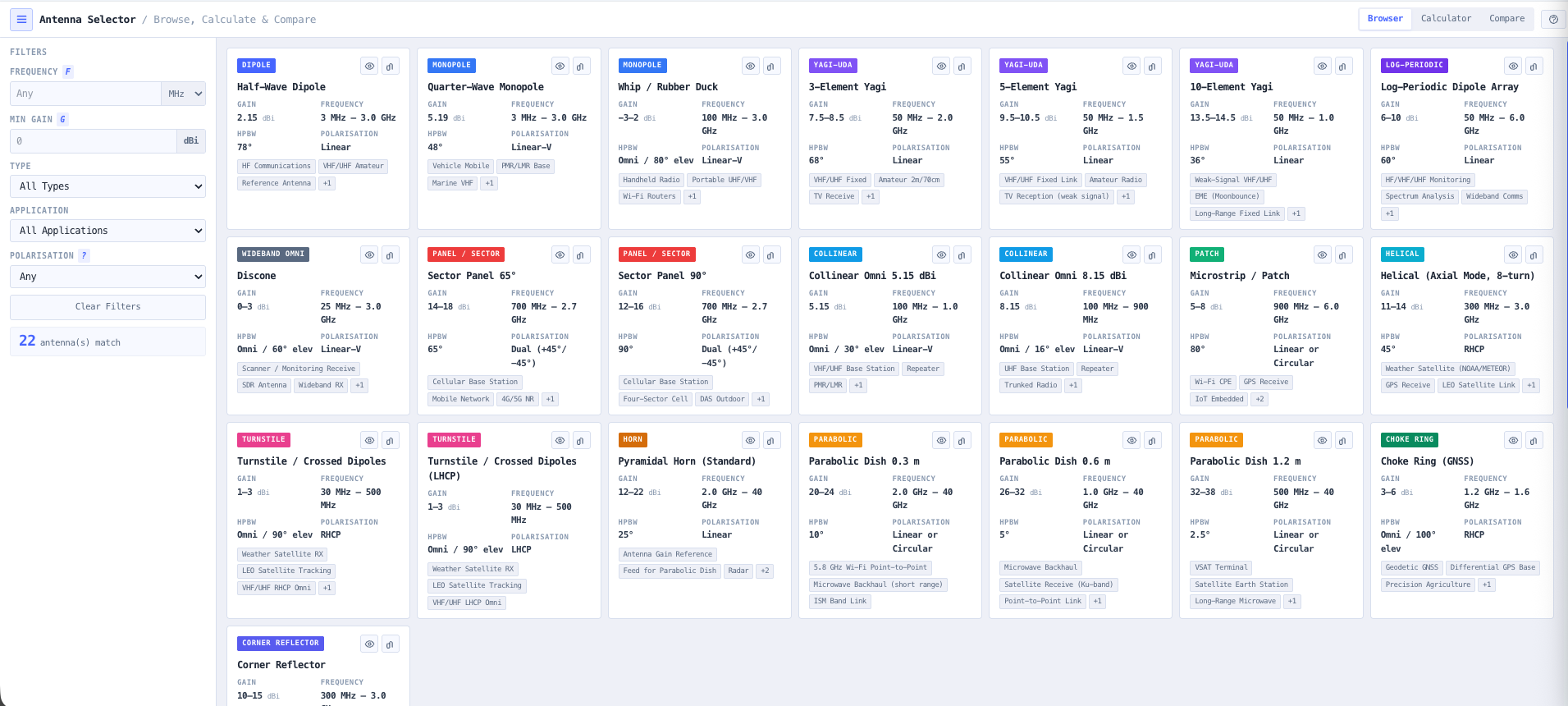
- Antenna Selector
Choose an antenna matched to the path lengths and takeoff angles, with siting notes for the remote install.
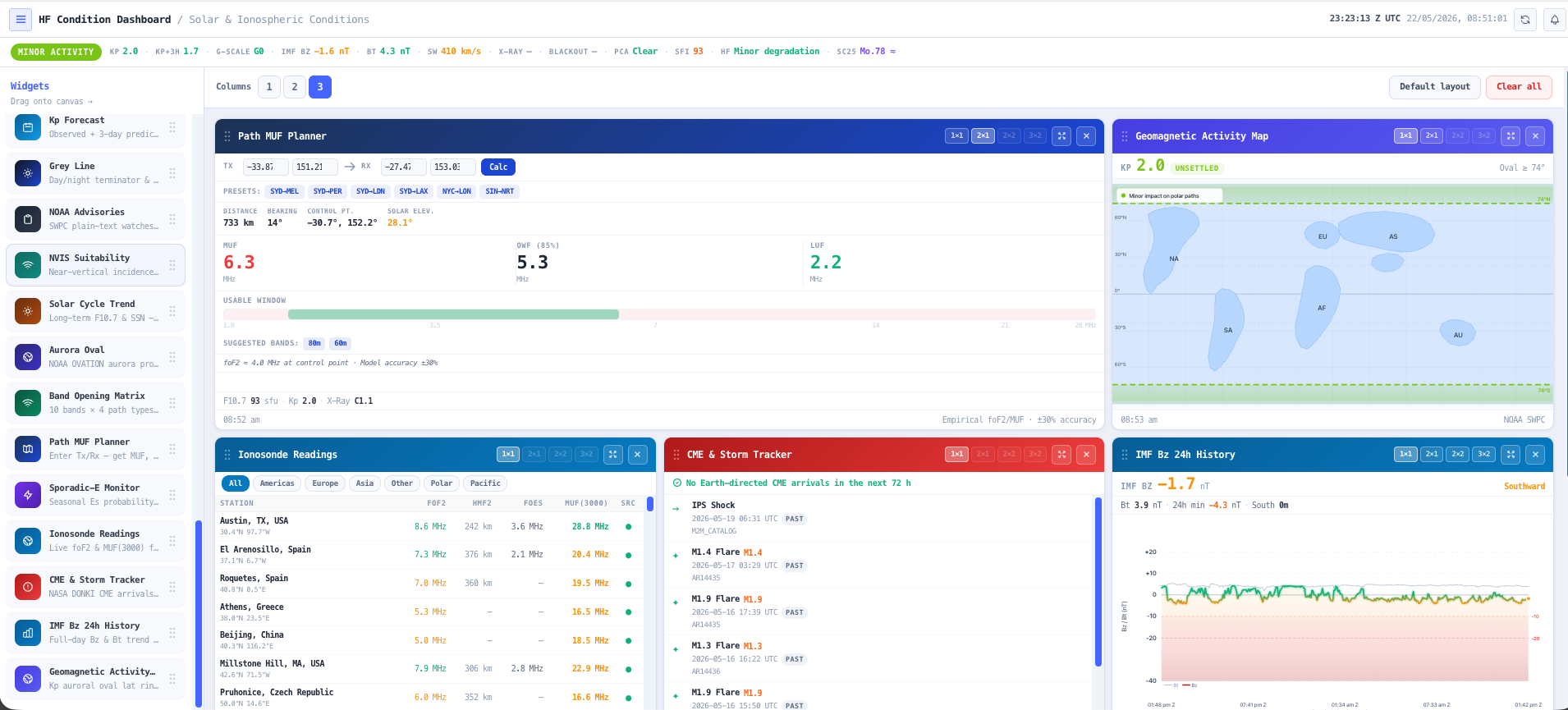
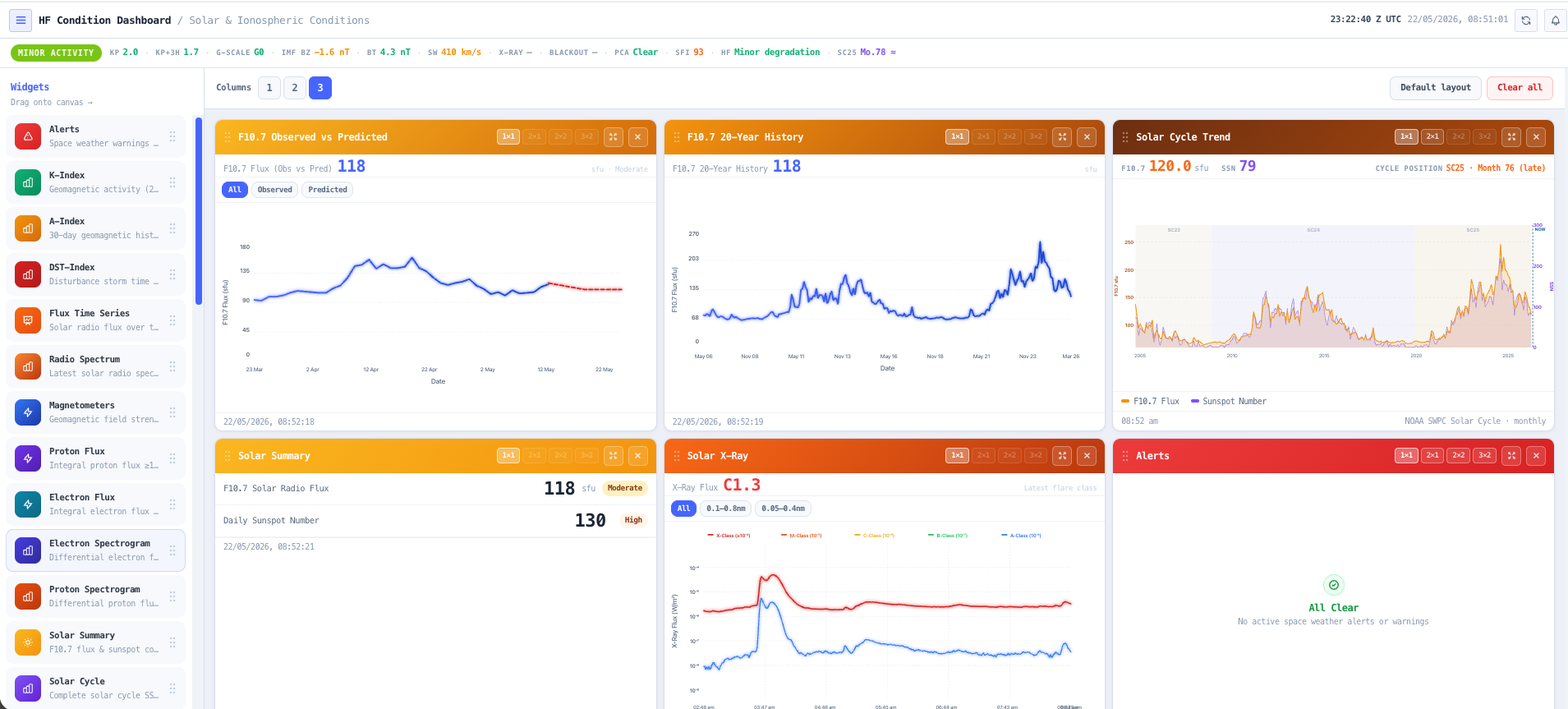
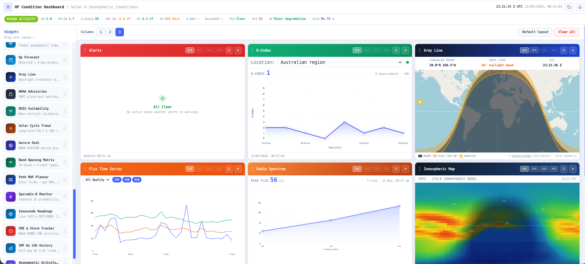
- Ionospheric Conditions Dashboard
Read current and forecast ionospheric conditions so the plan starts from where the band actually is, not an average.
- HF Link Planner
Model your real paths and build a frequency plan that survives the day-to-night transition and the seasons.
- RF EME Exposure Modeller
Map the RF exposure around the antenna and generate the exclusion zones and compliance report before anyone works near it.
What this gets you
- A frequency plan that holds through the day-to-night shift
- An antenna matched to the real paths, not a guess
- Propagation tied to live conditions, not a seasonal average
You walk away with: A day and night HF frequency plan tied to real propagation, an antenna matched to the paths so the network stays up when conditions shift, and an RF exposure compliance report for the site.
Prove fleet radio coverage before you buy metal
A fleet network only matters where the fleet actually drives. Before anyone signs a purchase order, you want the channel set coordinated and clean and the coverage demonstrated. This chain does it on screen.
2 steps in this workflow use tools that are coming soon, marked below.
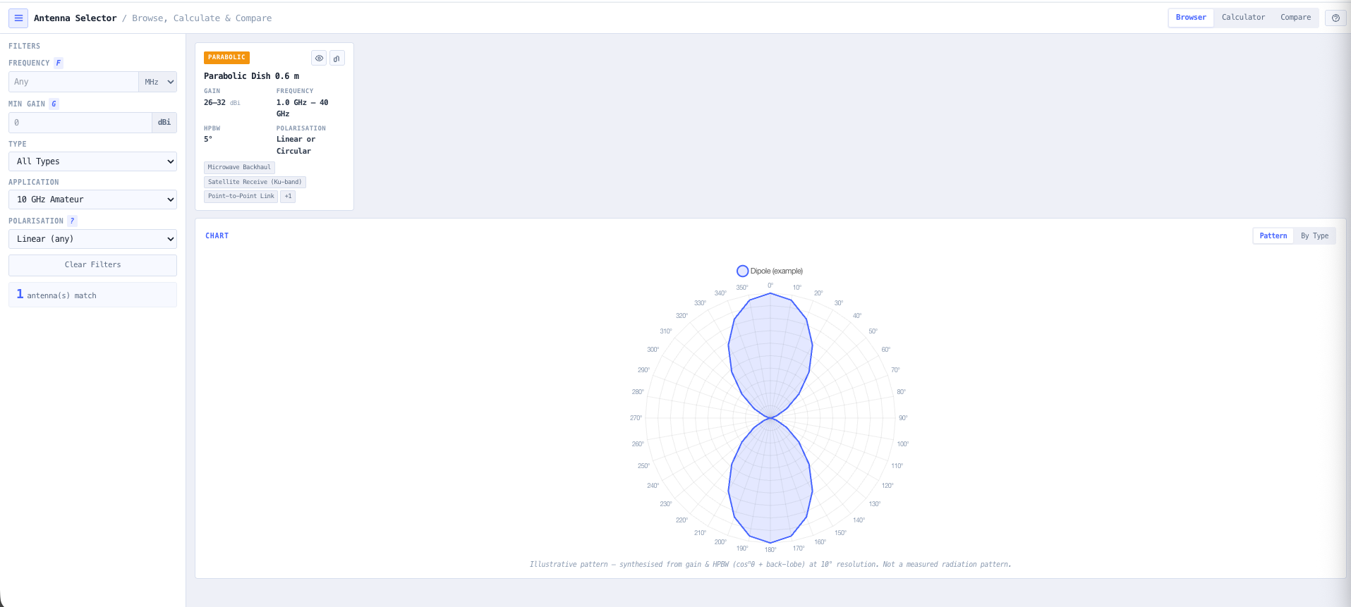
- Antenna Selector
Match an antenna and downtilt to each site so coverage lands where the fleet works, not over empty ground.
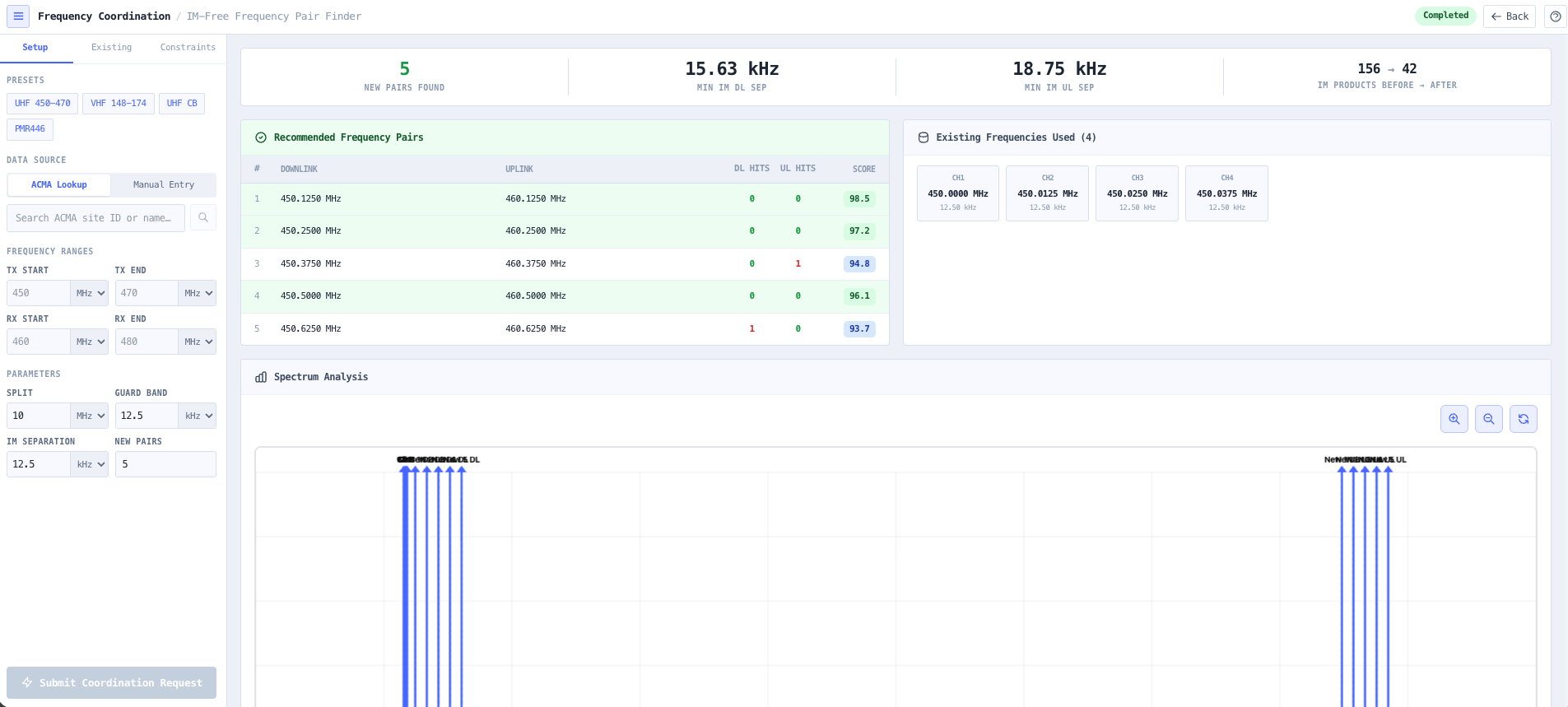
- Frequency Coordination Tool Coming soon
Coordinate the channel set against incumbents in the area before it goes anywhere near a regulator.
- Intermodulation Calculator
Confirm the channels do not generate intermod products that swamp your own receivers on a busy site.
- Coverage Predictor Coming soon
Predict coverage across the operational area at the design frequency and find the holes before they cost you a shift.
- RF EME Exposure Modeller
Model the RF exposure at each base station and export the ARPANSA compliance report and exclusion zones.
What this gets you
- Coverage proven before a purchase order is signed
- A coordinated, intermod-clean channel set ready for the regulator
- The holes found on a map, not after a shift goes dark
You walk away with: Per site antenna choices, a coordinated and intermod-clean channel set, a coverage map at the design frequency, and an RF exposure compliance report for each site, ready to take to the regulator.
Design an antenna and prove it on the map
A site needs a specific pattern, not whatever is on the shelf. You want to shape the antenna, read its gain and beamwidth, then drop it on the real terrain and watch the coverage it actually delivers before you commit to it. This chain takes you from element to exposure zone.
2 steps in this workflow use tools that are coming soon, marked below.
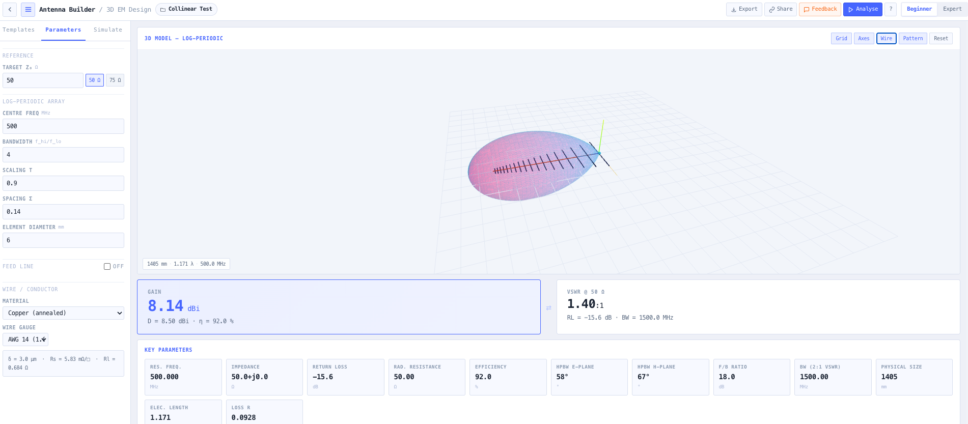
- Antenna Builder Coming soon
Build the antenna from its elements and read the modelled pattern, gain, and front-to-back ratio.
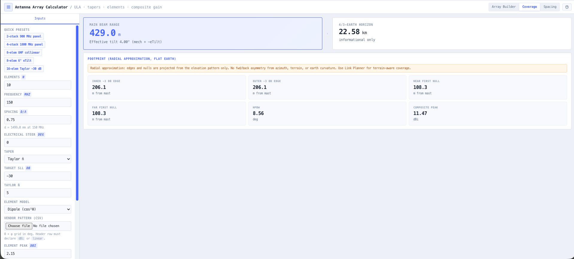
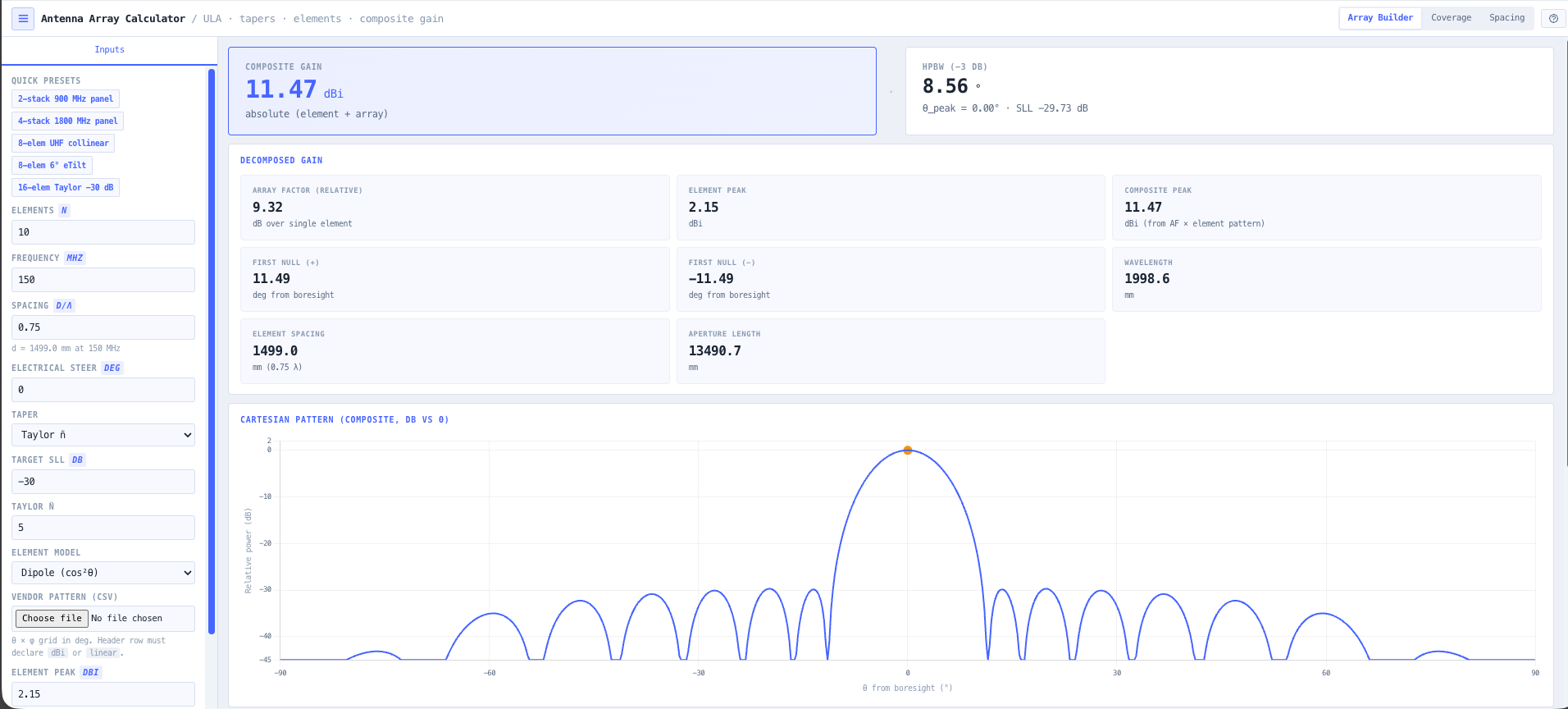
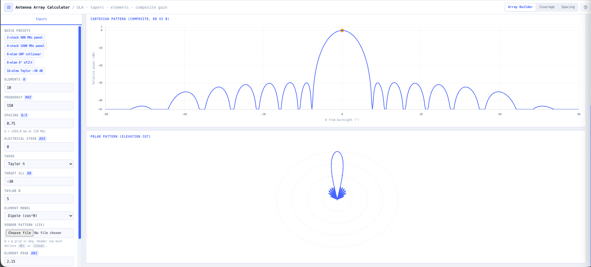
- Antenna Array Calculator
Stack elements into an array and shape the pattern and gain for the coverage you are chasing.
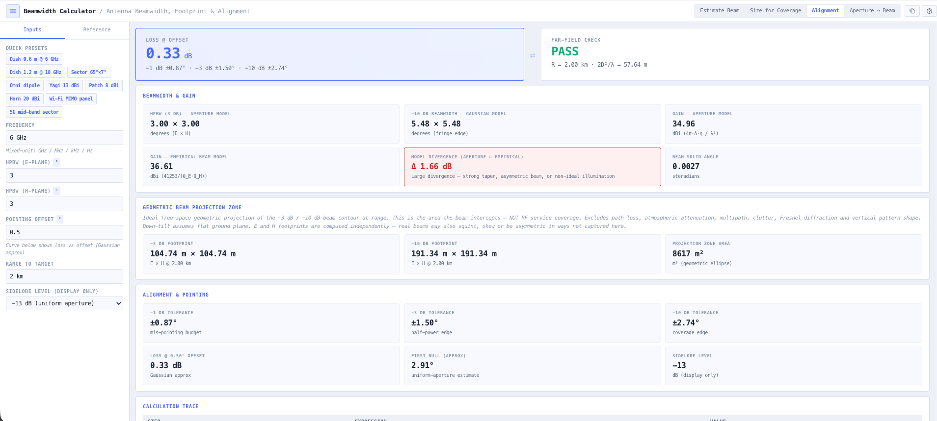
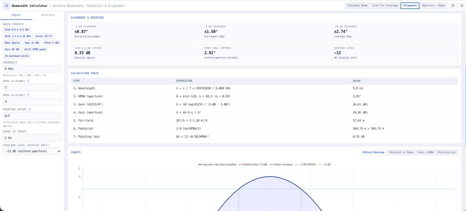
- Beamwidth Calculator
Check the horizontal and vertical beamwidth so the main lobe lands where the traffic is.
- Coverage Predictor Coming soon
Drop the antenna onto the real terrain and see the coverage it delivers across the operational area.
- RF EME Exposure Modeller
Model the exposure zones around the finished antenna and export the compliance report.
What this gets you
- A pattern shaped to the job, not whatever is on the shelf
- Coverage proven on real terrain before you commit
- Exposure zones and compliance sorted alongside the design
You walk away with: A shaped antenna design with a known pattern and gain, a coverage map on real terrain that proves it works, and an RF exposure compliance report for the site.
Spec the feeder system from radio to antenna
The feeder run is where quiet money leaks out of a system. Pick the wrong coax and half your power heats the cable; miss a bad connector and PIM swamps the receiver. This chain specs the run end-to-end and proves it before anyone climbs the tower.
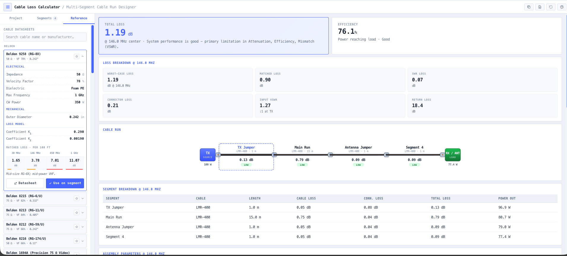
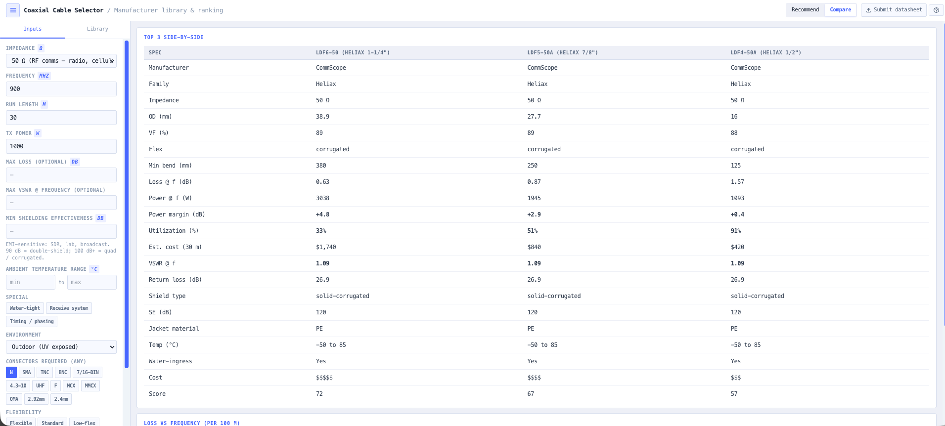
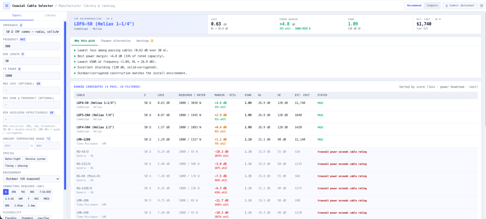
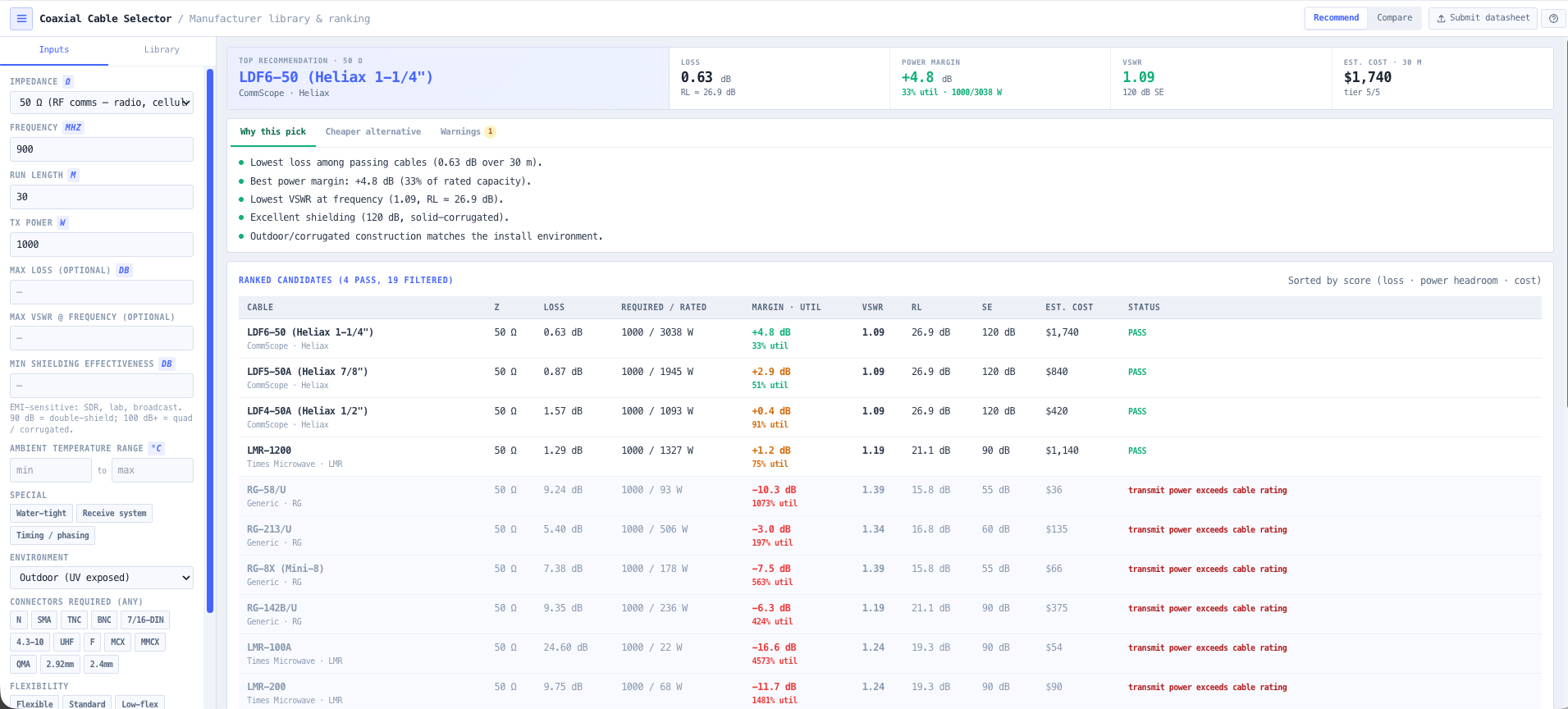
- Coaxial Cable Selector
Choose the coax for the frequency, power, and run length, with loss and velocity straight from the vendor specs.
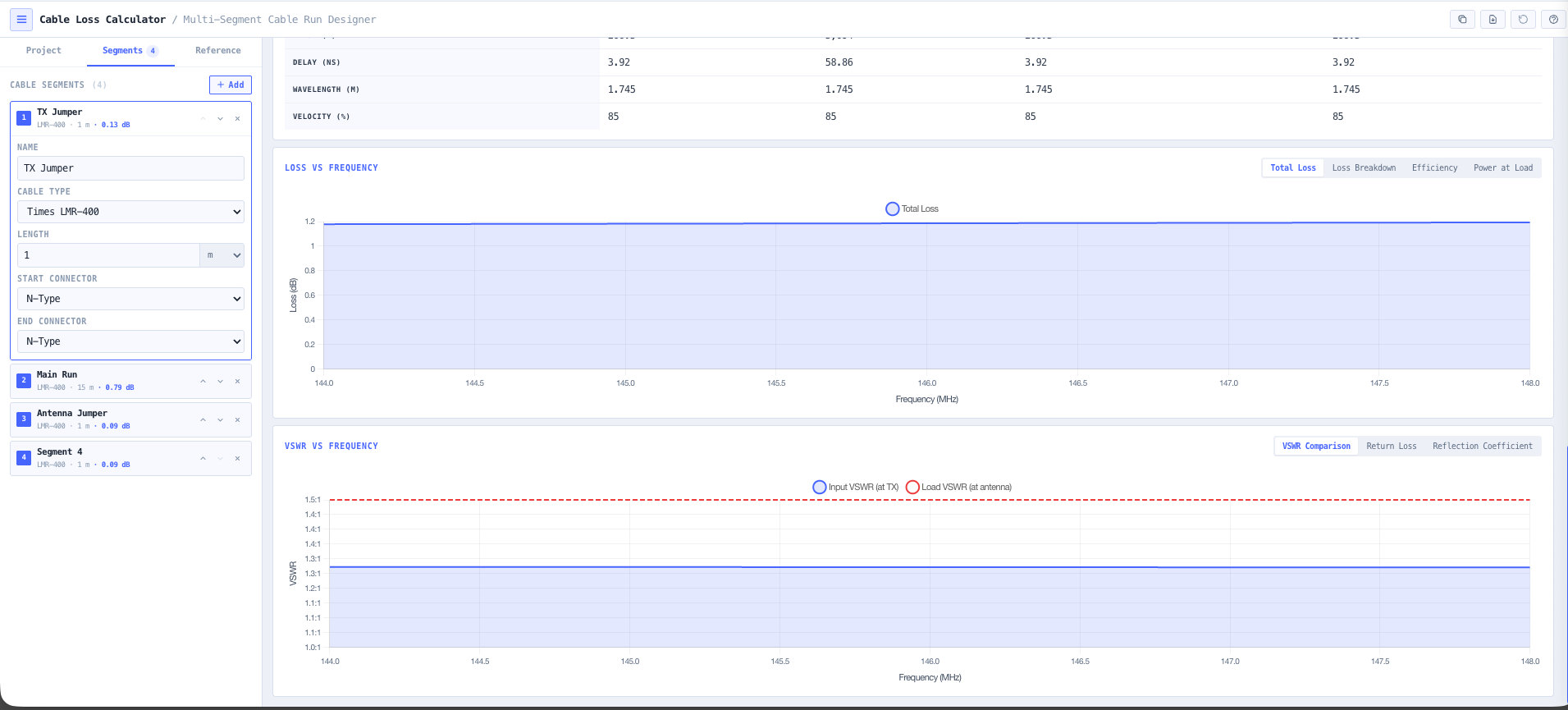
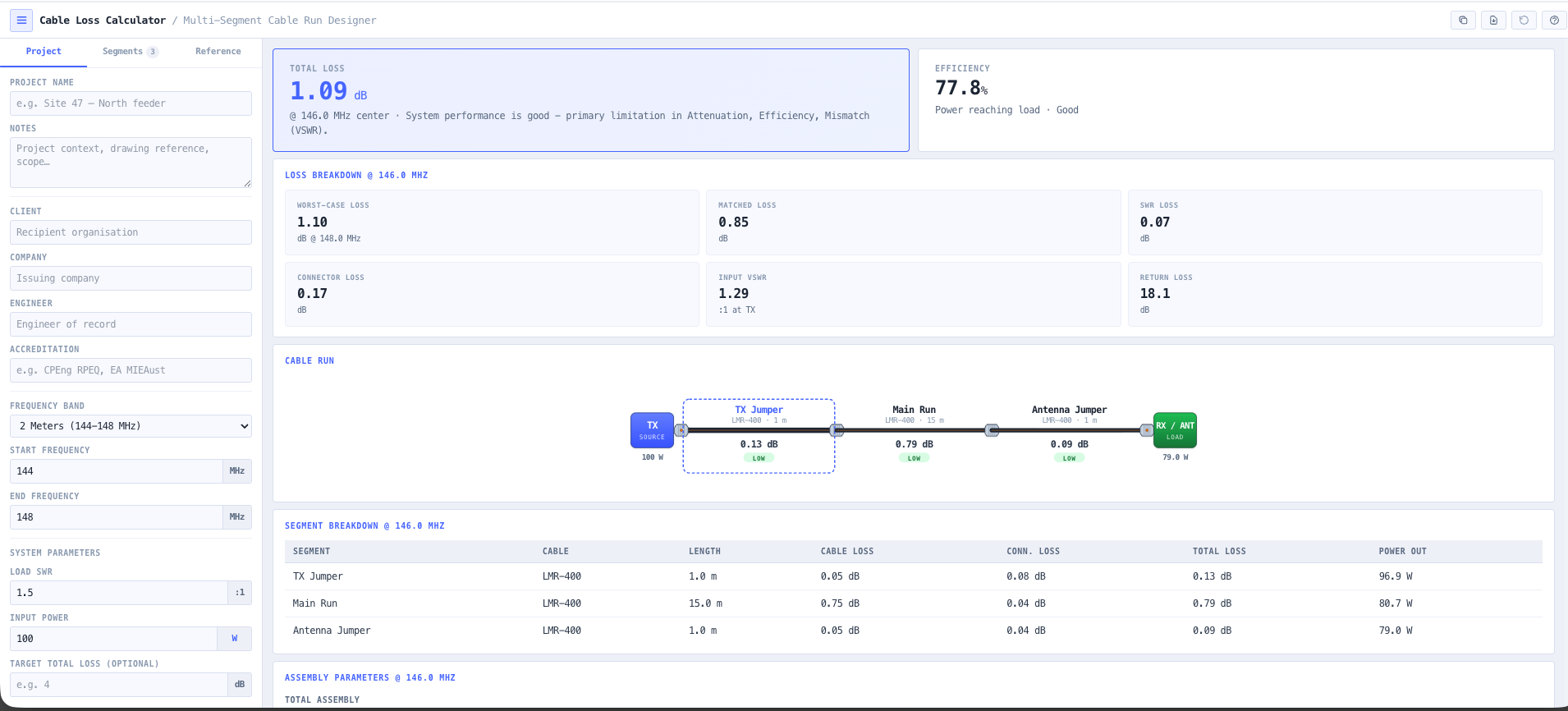
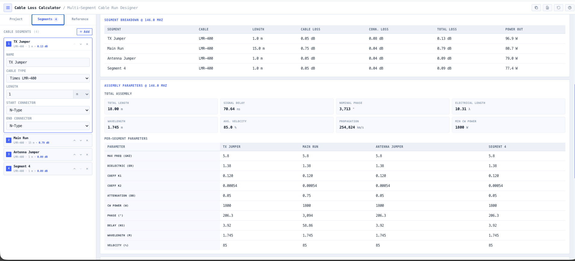
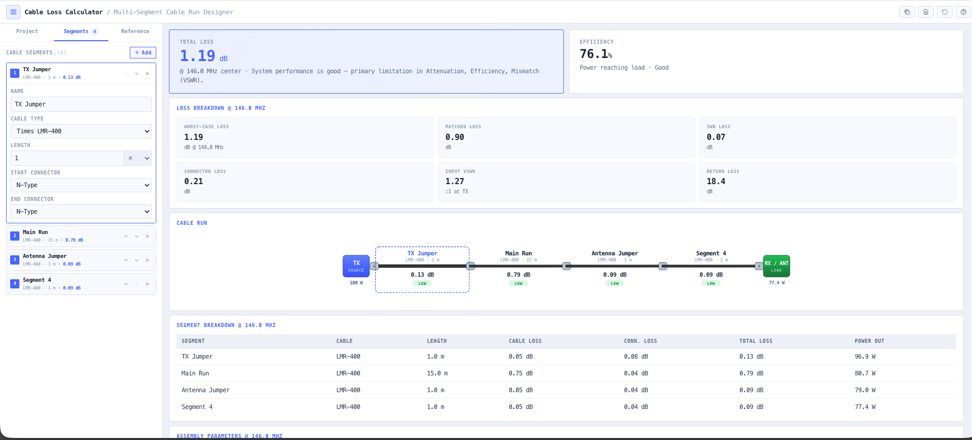
- Cable Loss Calculator
Budget the loss across the full run so you know exactly what reaches the antenna port.
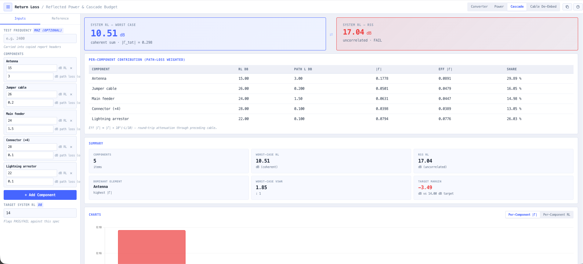
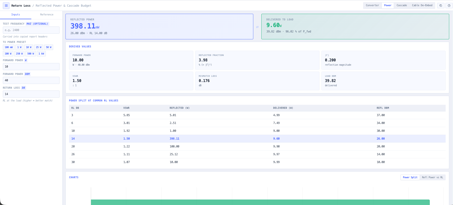
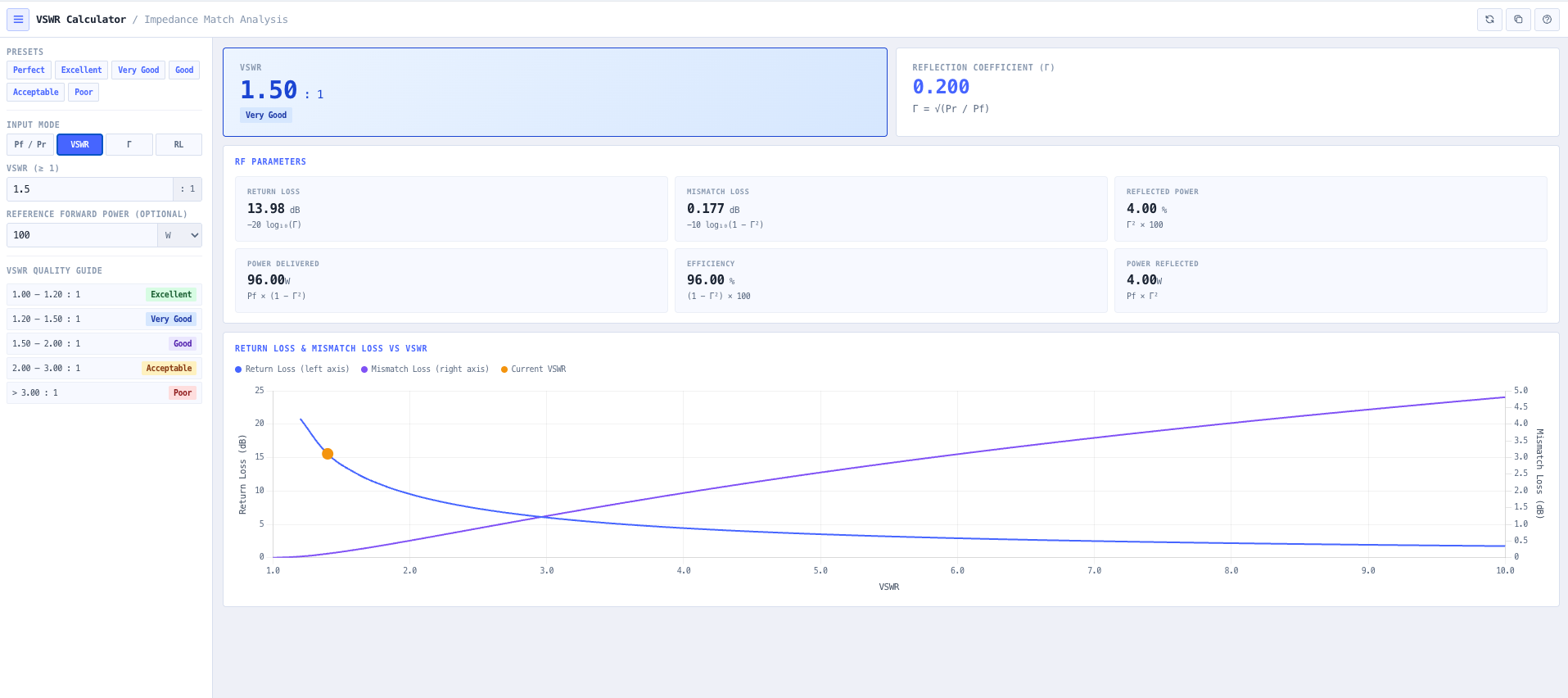
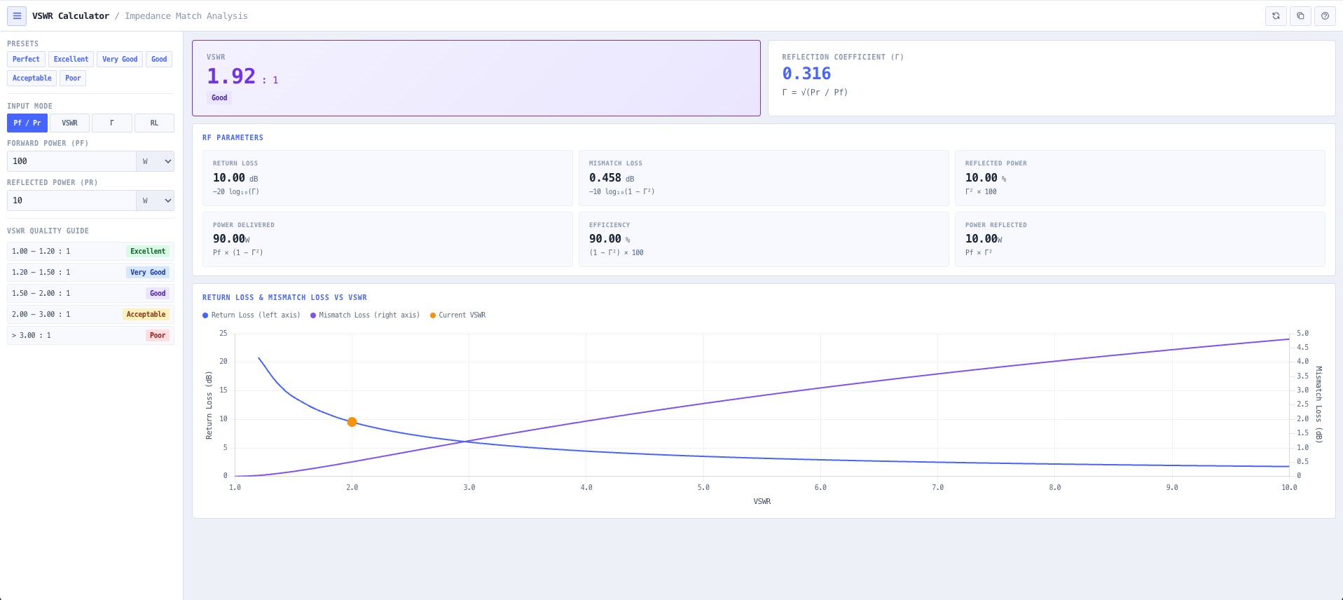
- VSWR Calculator
Check the match and see how much power the mismatch sends back down the line.
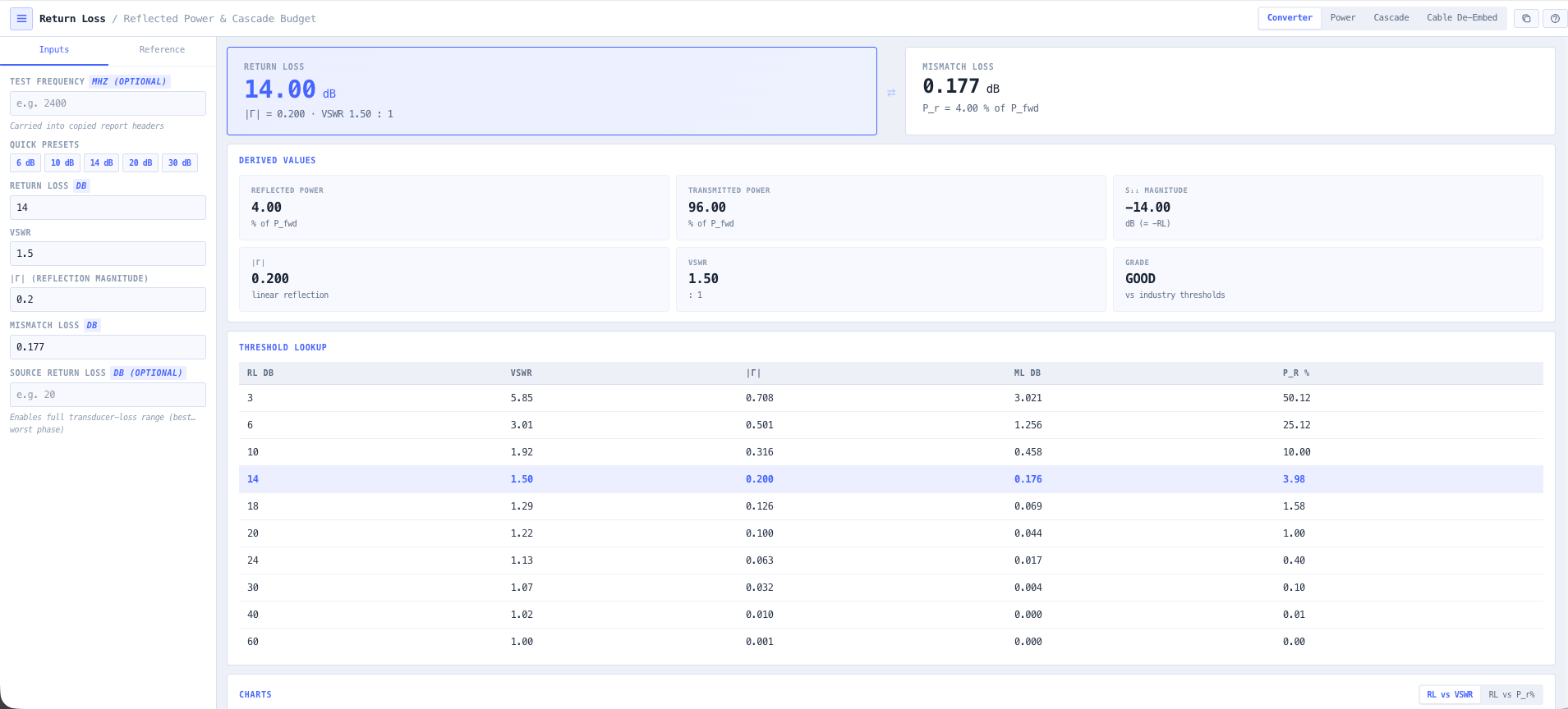
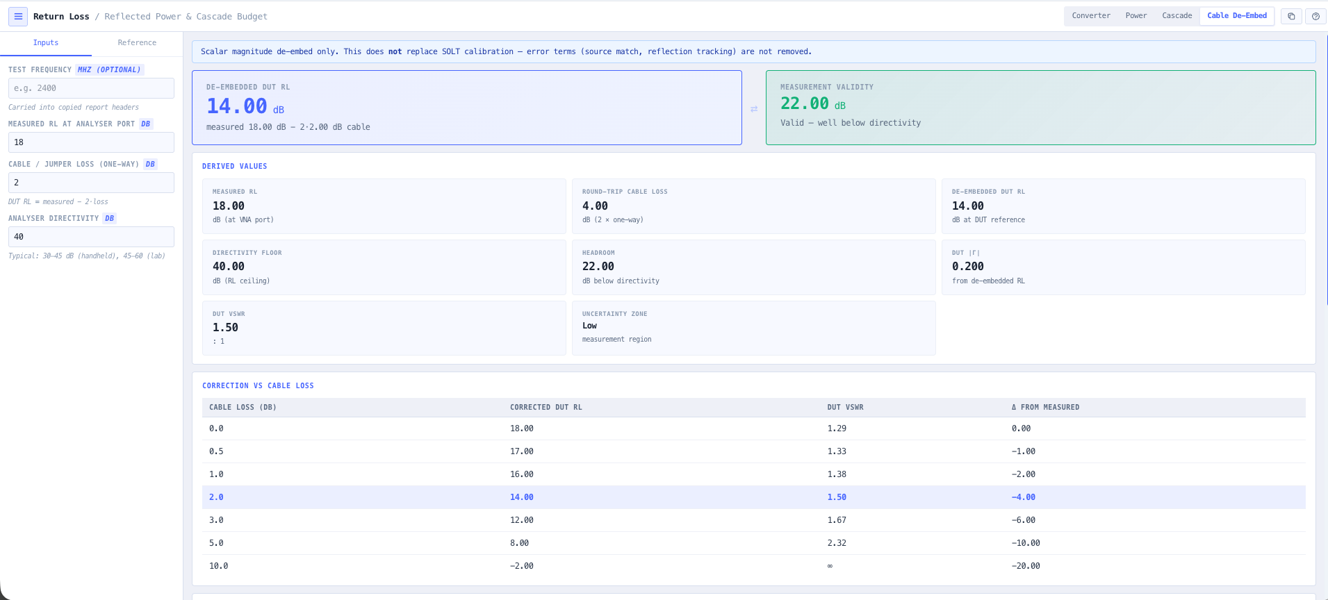
- Return Loss Calculator
Convert the match into the return loss figure your acceptance test will measure against.
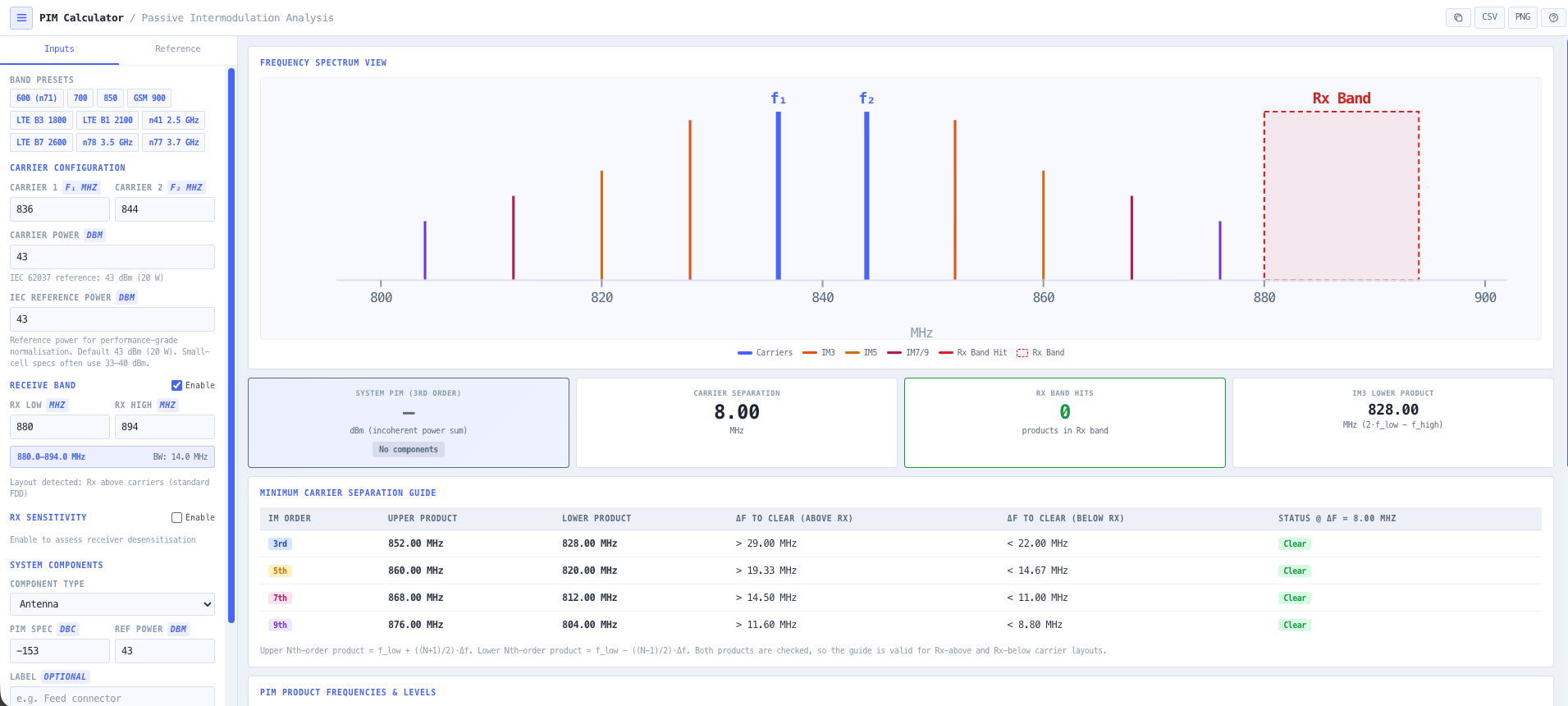
- PIM Calculator
Estimate the passive intermodulation a marginal connector will throw into your own receiver.
What this gets you
- Every dB of feeder loss budgeted to the antenna port
- Match, return loss and PIM figures ready for the acceptance test
- The quiet losses caught before anyone climbs the tower
You walk away with: A specified feeder run with the right coax, a loss budget to the antenna port, and match, return loss, and PIM figures ready for the acceptance test.
Power a remote comms site that never drops
Radios are useless without power, and a remote site has no mains to lean on. You need solar and battery sized for the worst run of weather, a generator behind it, and earthing that survives a strike on the mast. This chain builds the power system around the comms load.
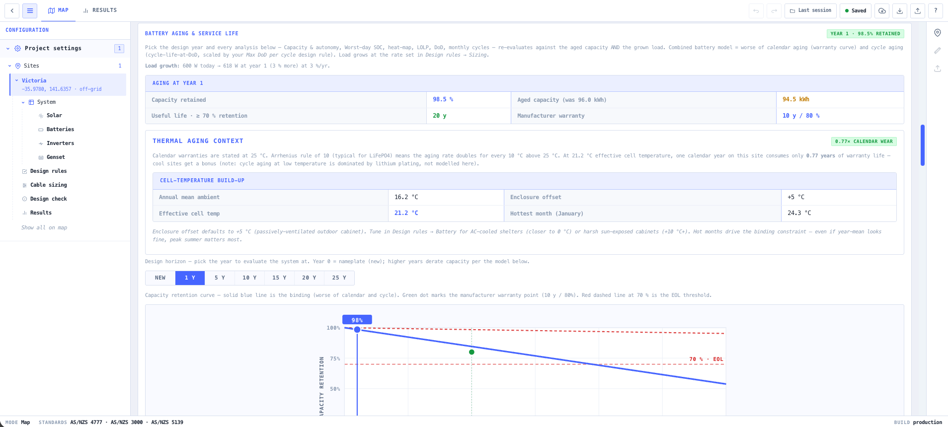
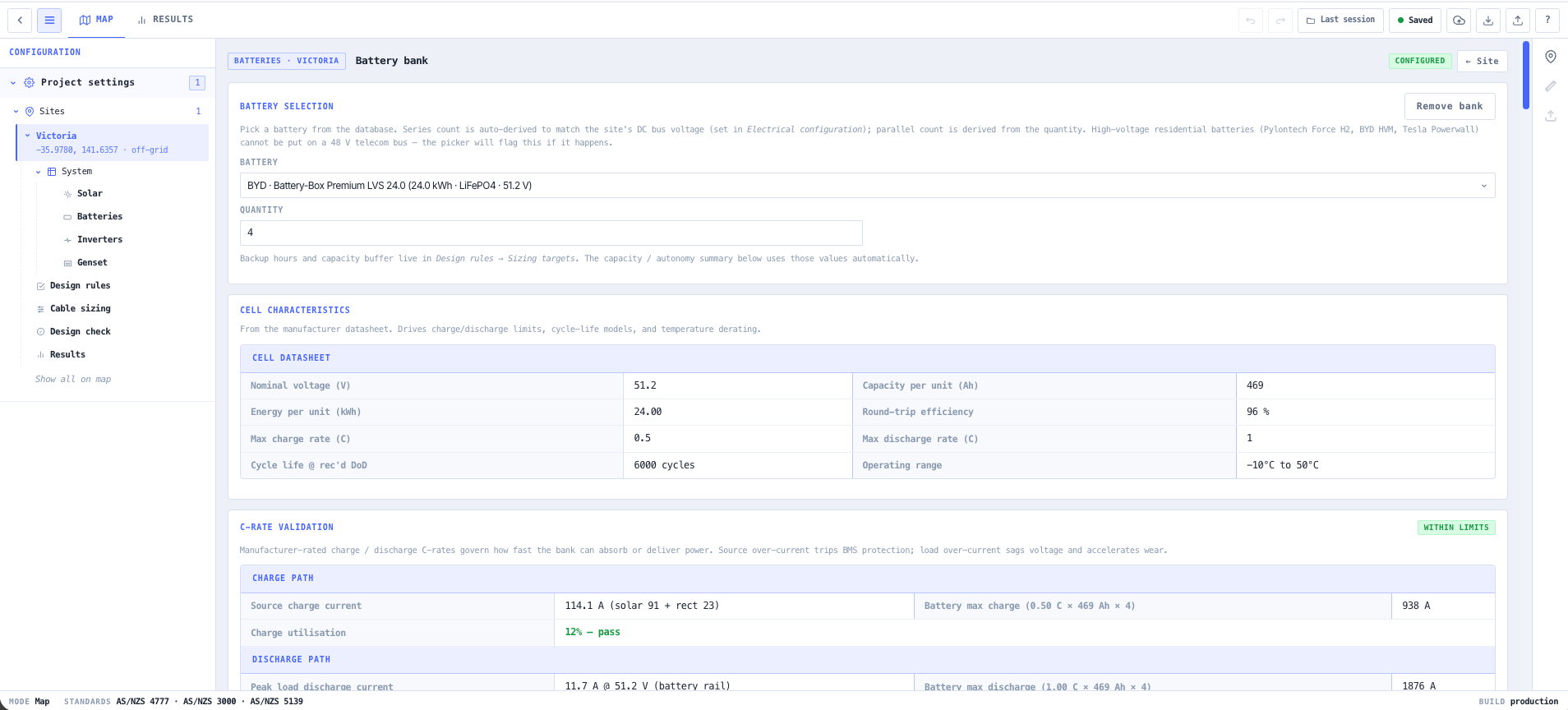
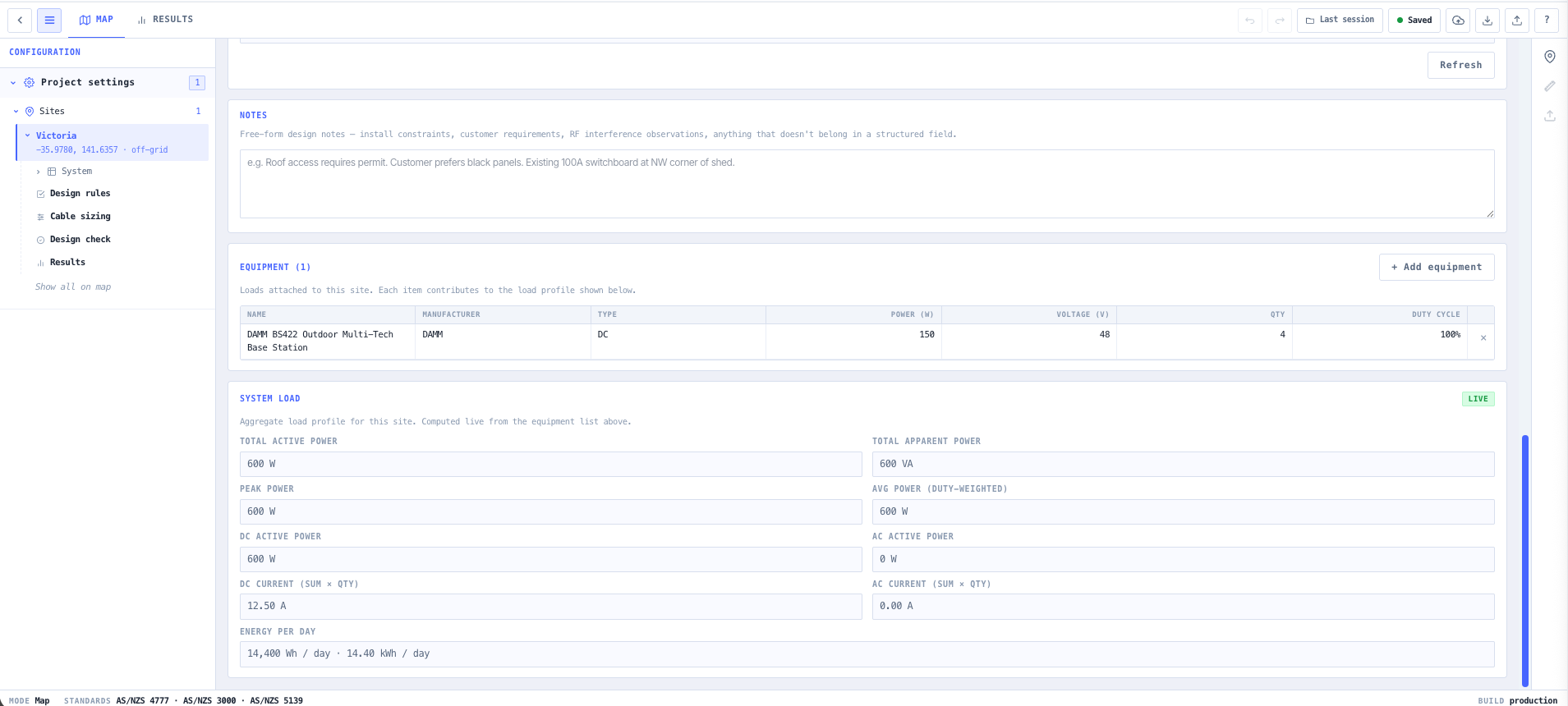

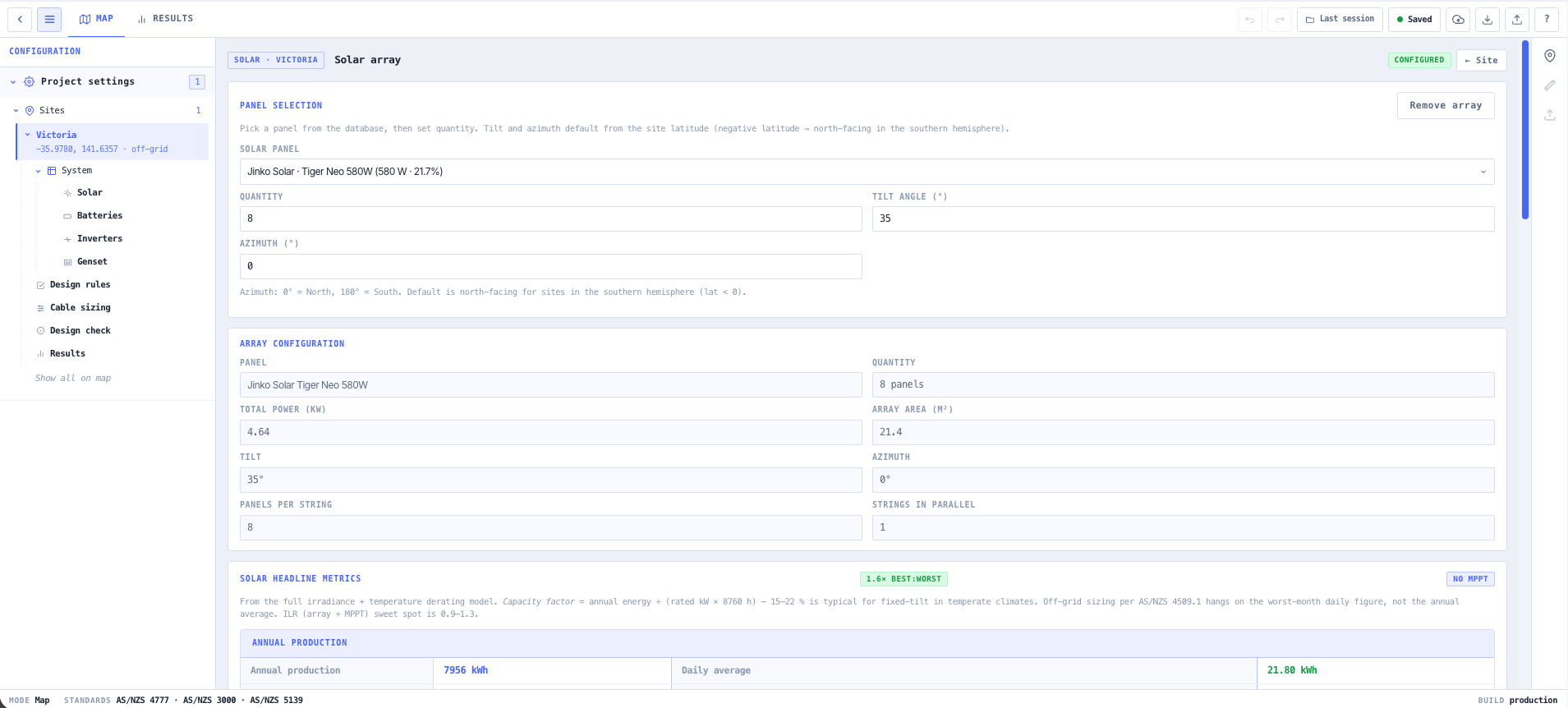
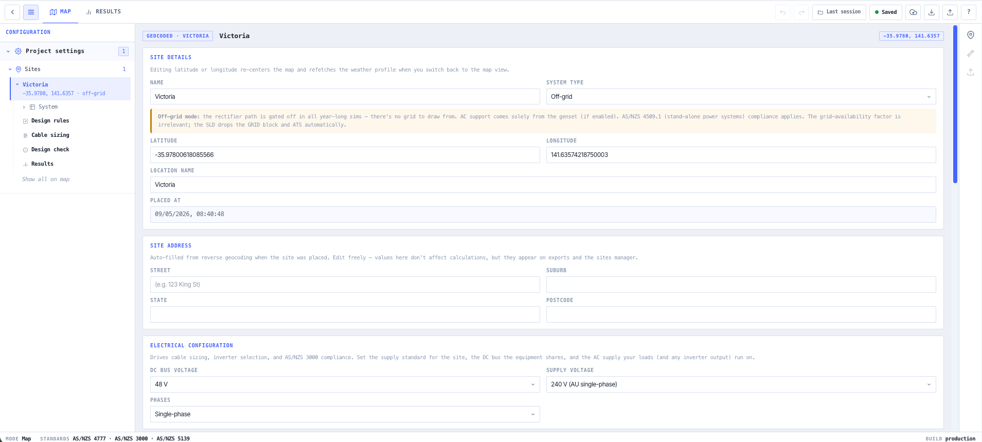
- BESS & Solar System Designer
Size the solar array and battery bank for the site load and the autonomy you need through a long run of cloudy days.
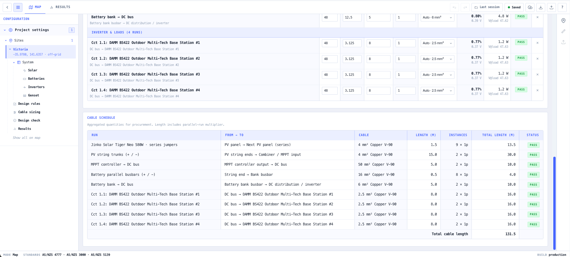
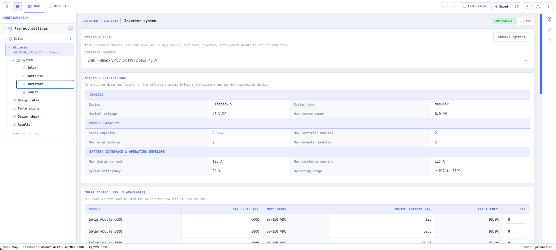
- DC Power System Designer
Lay out the DC distribution, rectifiers, and battery string that keep the radios alive when the source drops away.
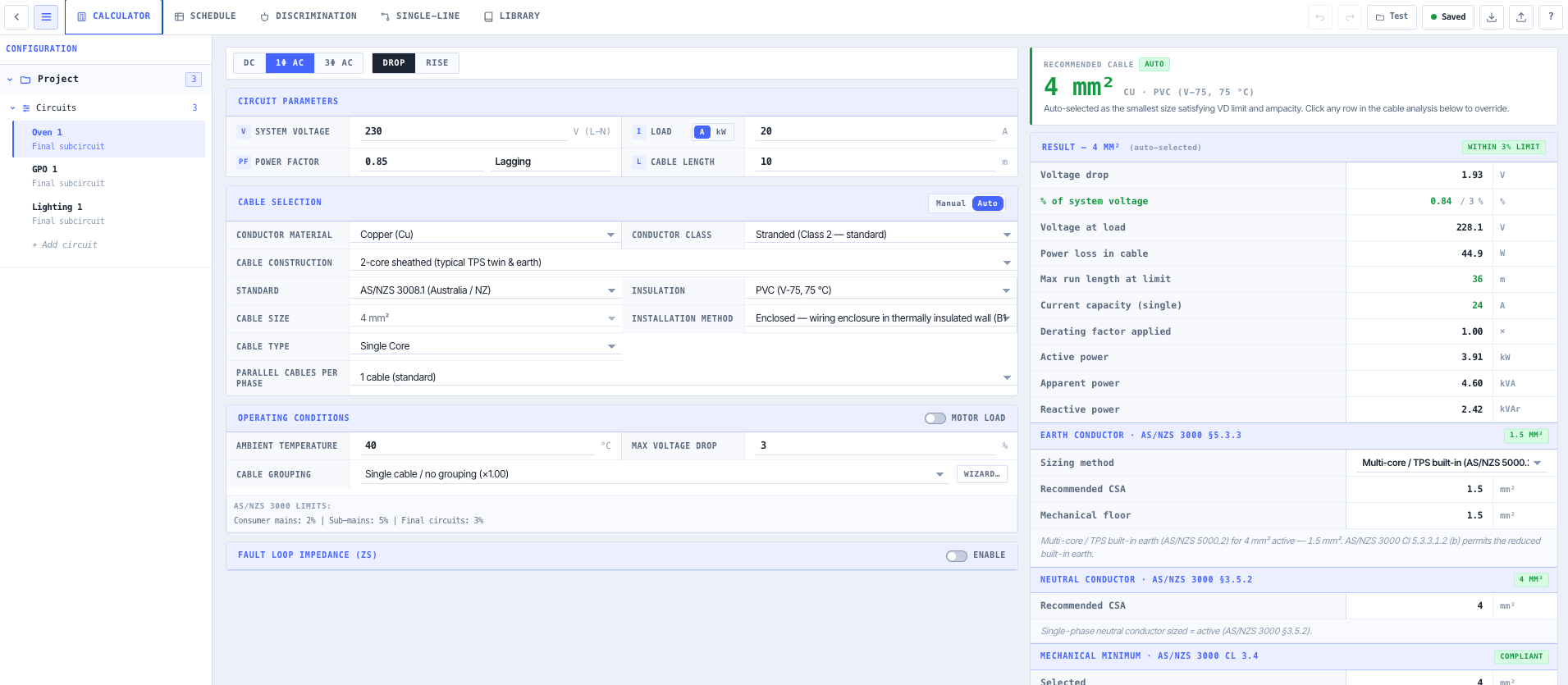
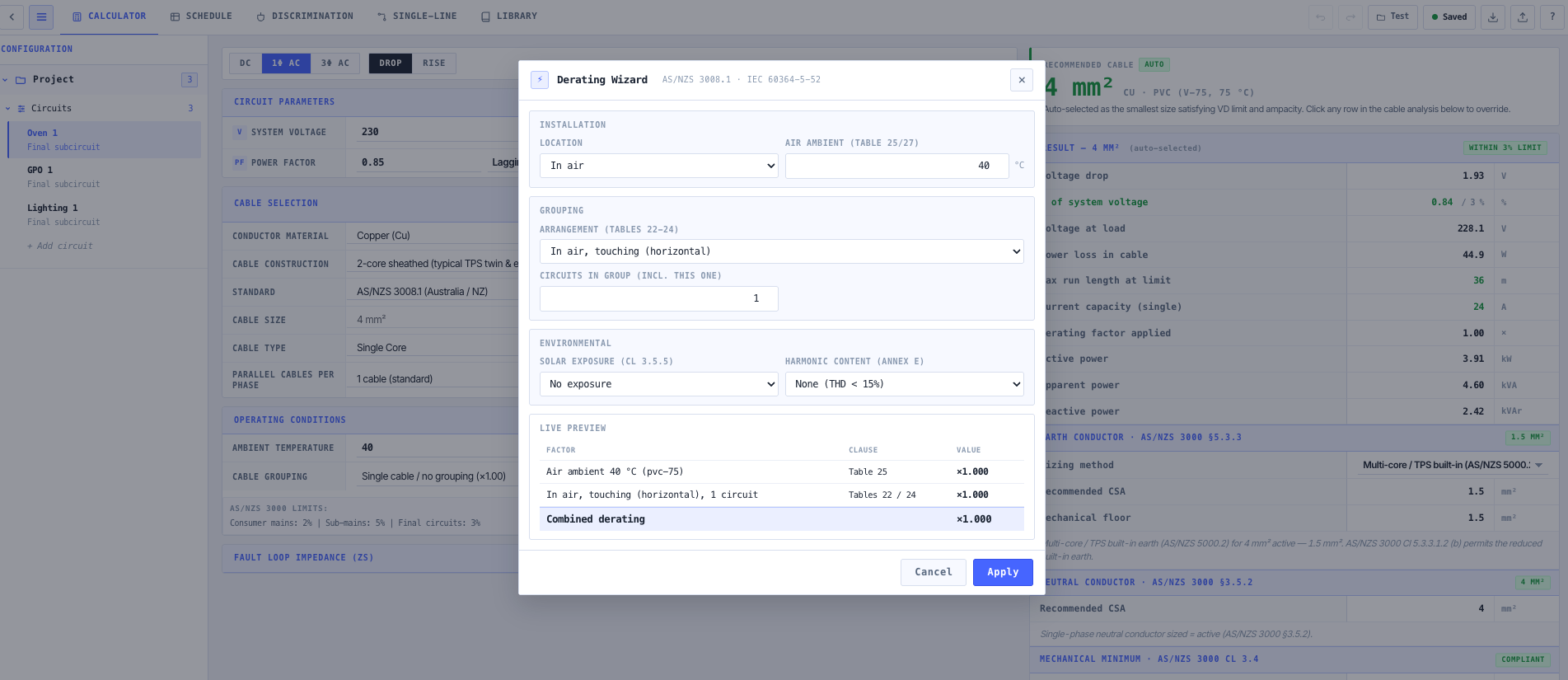
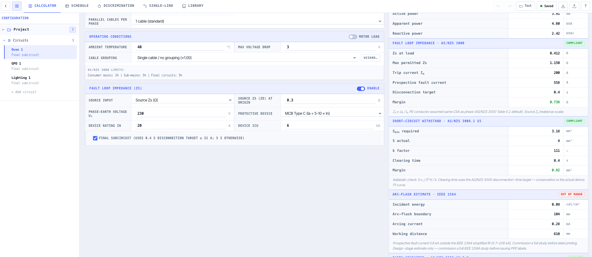
- Cable Sizing & Voltage Drop
Size every feeder so voltage drop stays inside limits across the longest cable run on the site.
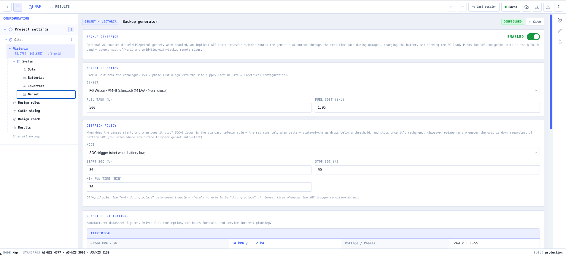
- Generator Sizing Calculator
Size the standby generator to the real load profile, including the surge when everything restarts at once.
- Earthing & Lightning Protection Calculator
Design the earthing and lightning protection so a strike on the mast does not take the whole site with it.
What this gets you
- Solar and battery sized for the worst run of weather
- Voltage drop held inside limits across the longest run
- Earthing and lightning protection matched to a strike on the mast
You walk away with: A full site power design. Solar and battery sizing, DC distribution, feeder cable sizing, generator backup, and earthing and lightning protection matched to the load and the environment.
Design a fibre PON access link end-to-end
A new fibre access network has to reach every premises with enough optical budget to spare, at the split ratio that makes the economics work. Too aggressive on the split and the far end goes dark. This chain sizes the split, proves the budget, and lays out the link.
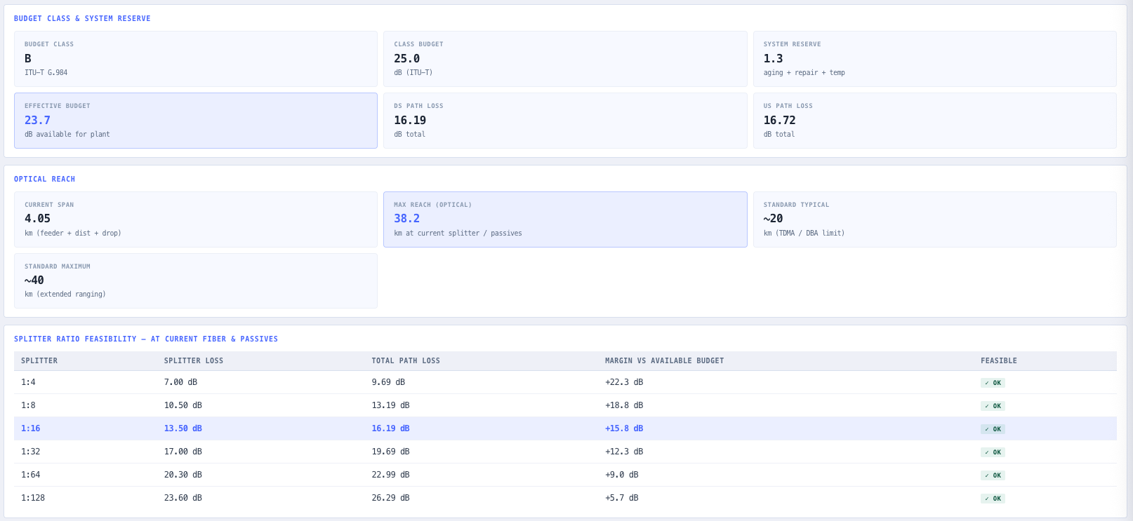
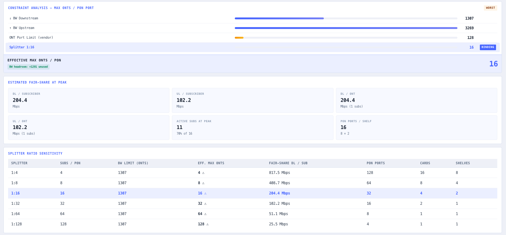
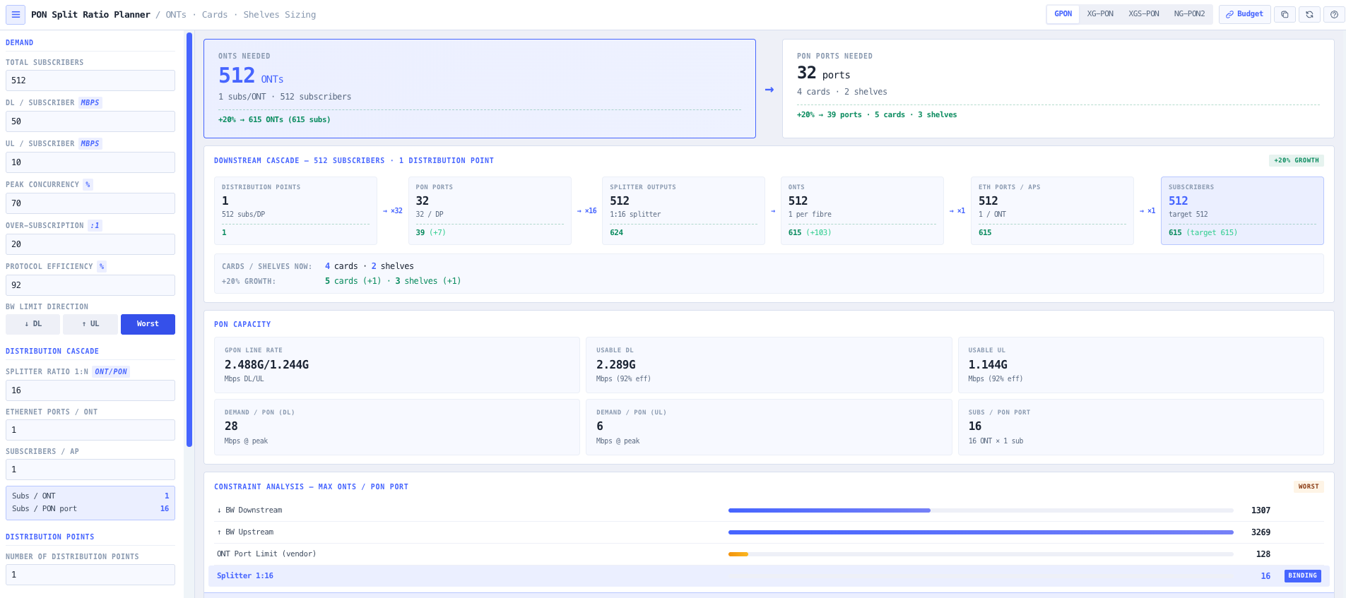
- PON Split Ratio Planner
Set the PON standard and the demand, then size the split ratio and distribution cascade for the premises you need to serve.
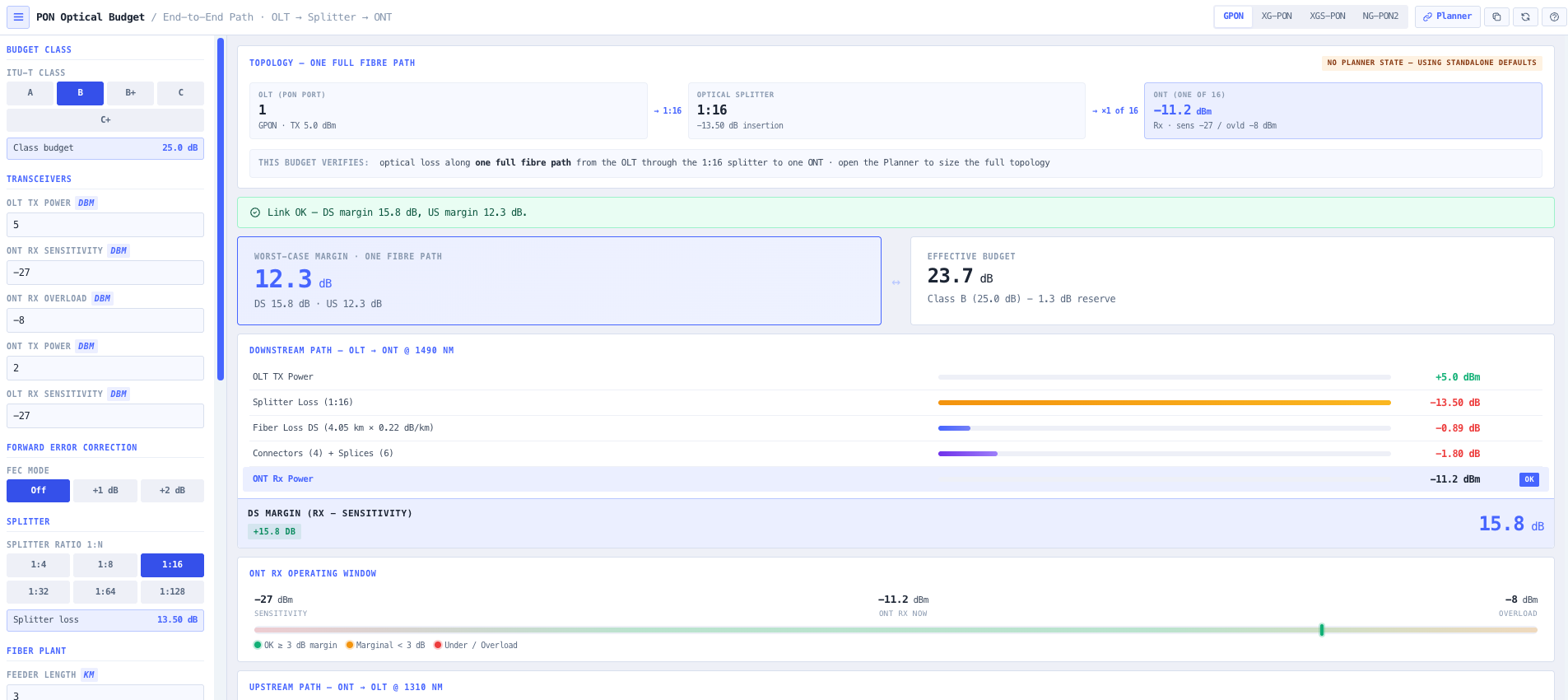
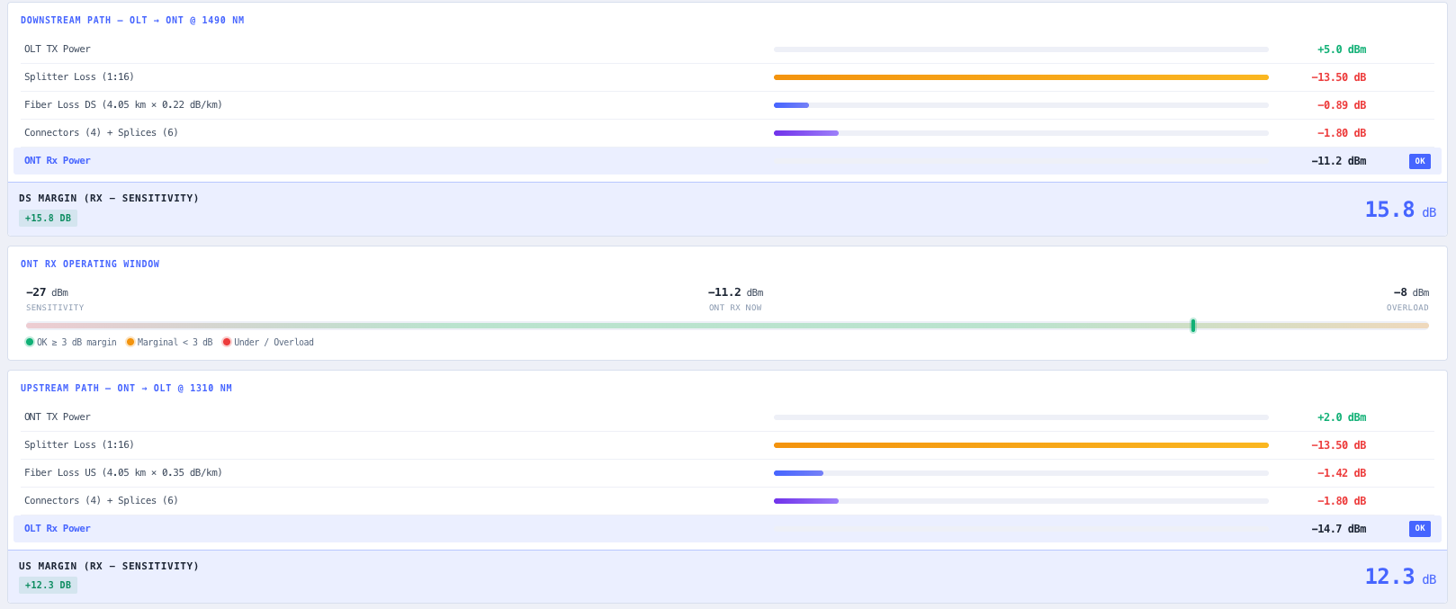
- PON Optical Budget Calculator
Prove the optical budget against the chosen class. Transceiver levels, splitter loss, and fibre plant against the reach you need.
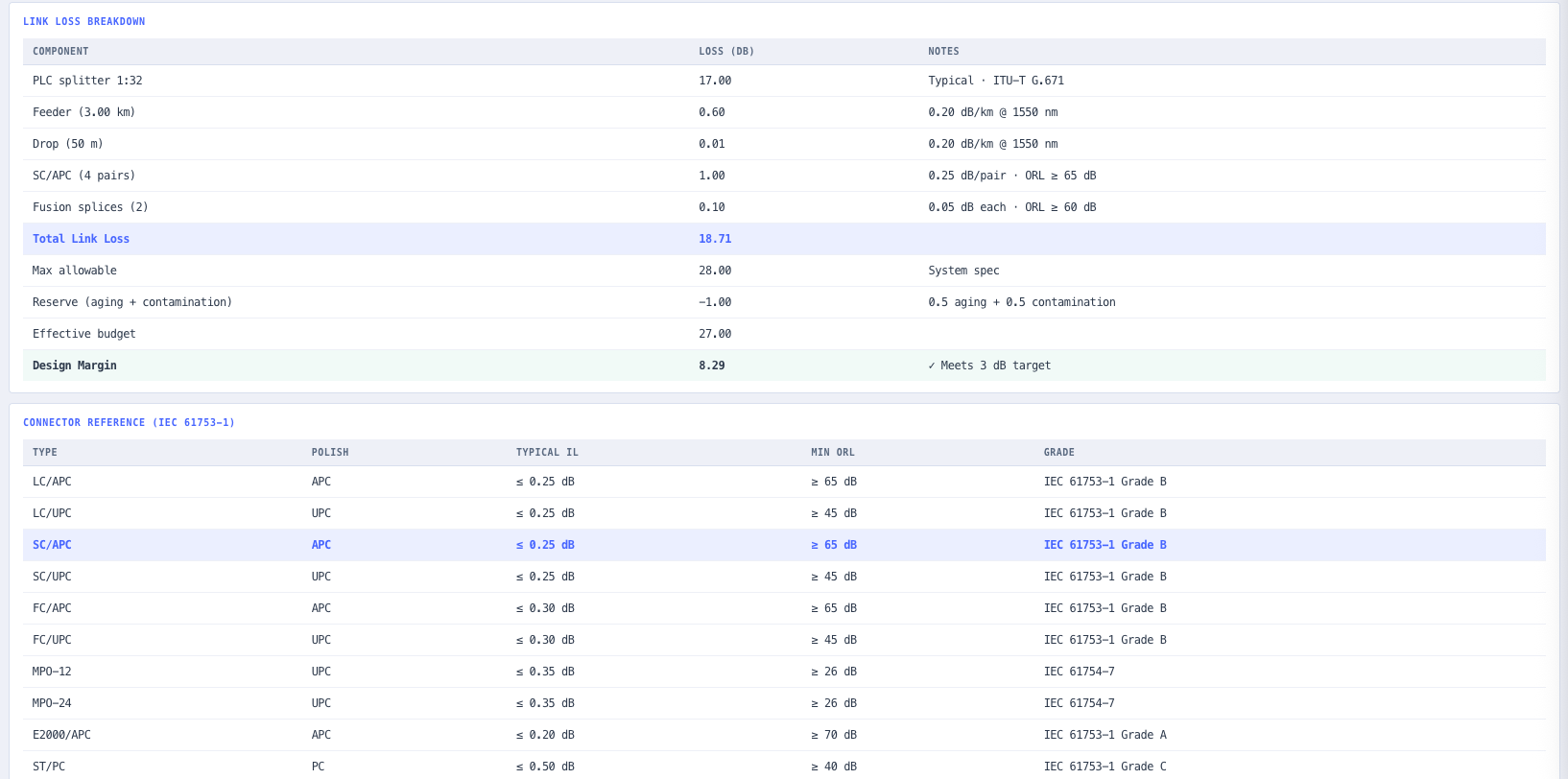
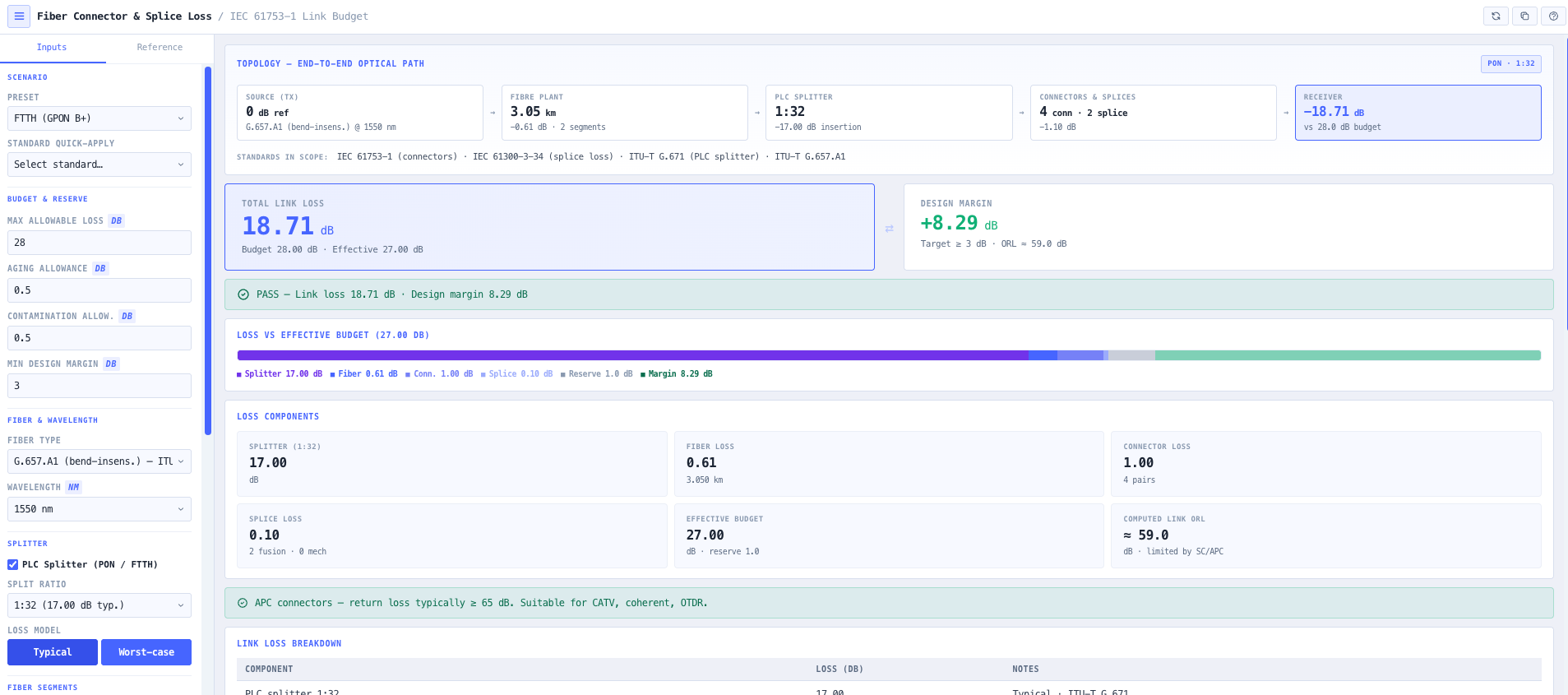
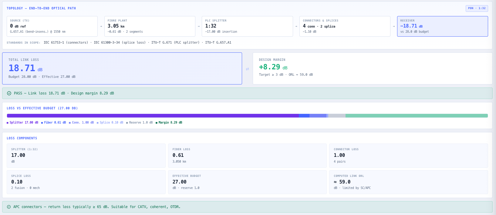
- Fibre Optic Connector and Splice Loss Calculator
Account for every connector, fusion splice, and mechanical splice so the field loss is in the budget, not a surprise at test.
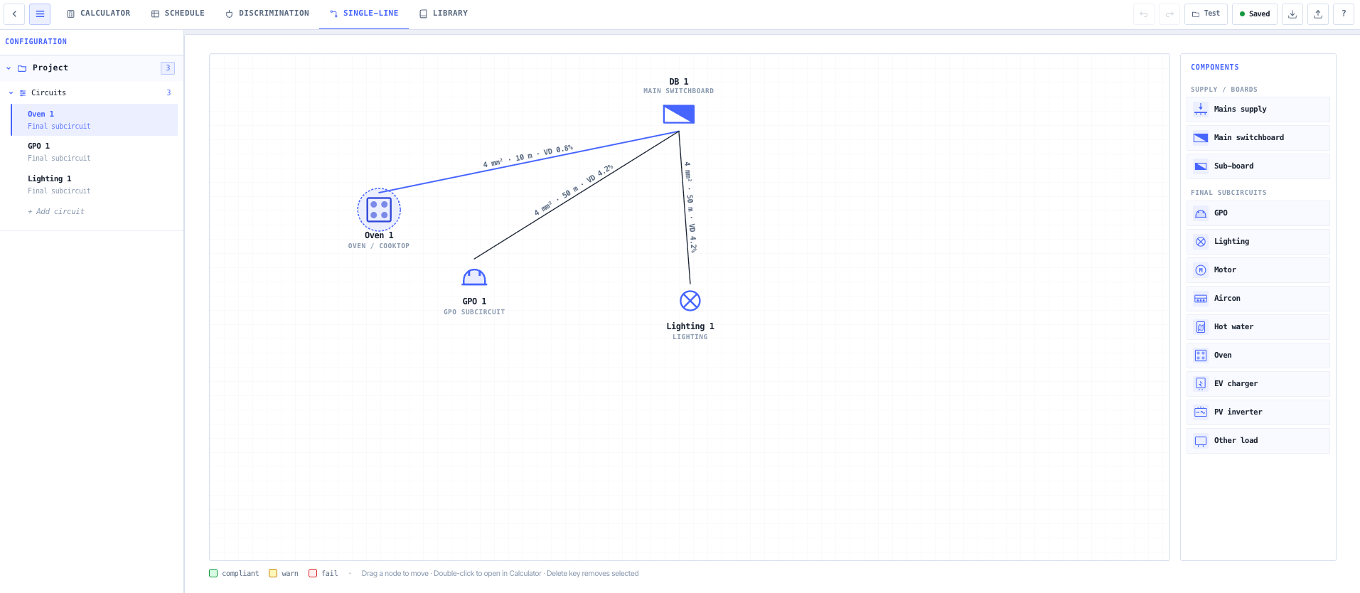
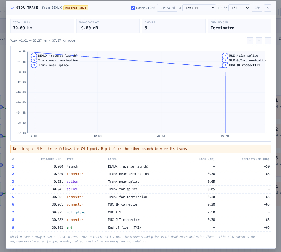
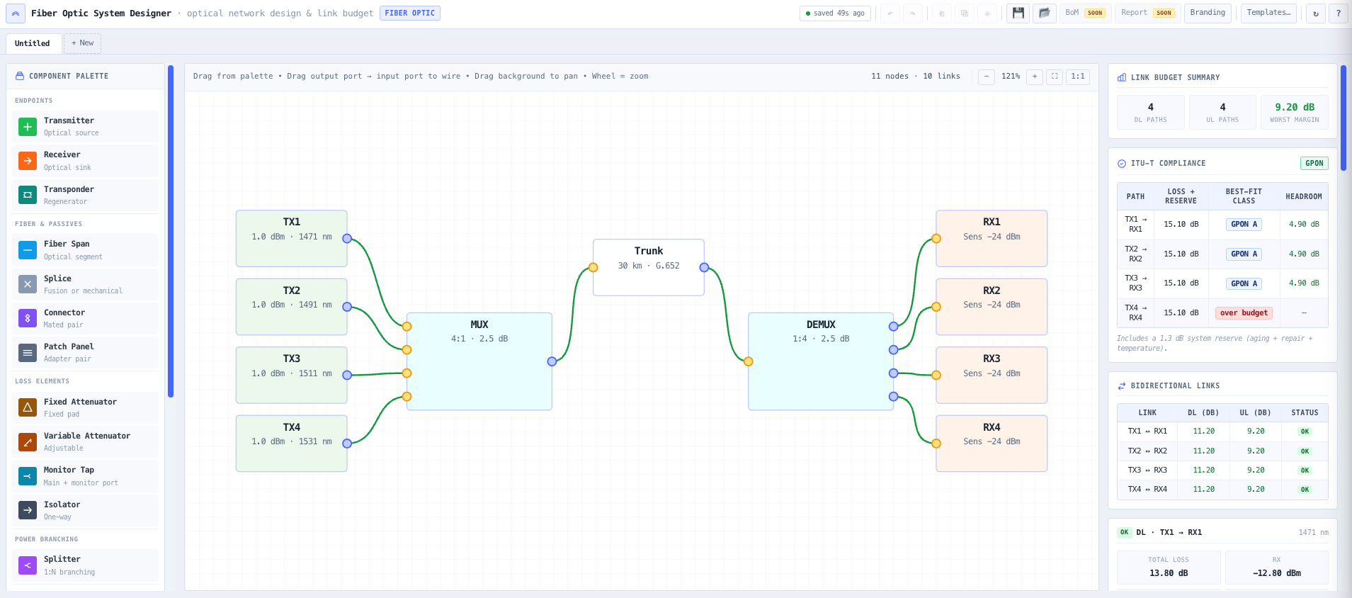
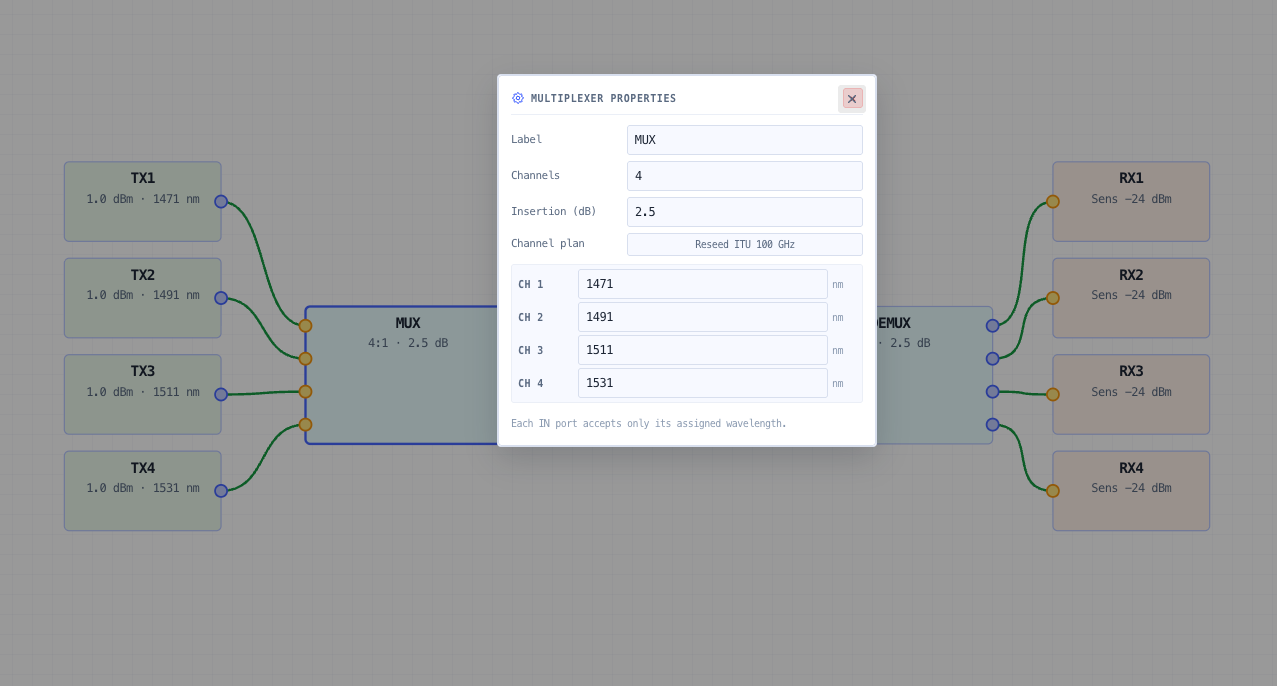
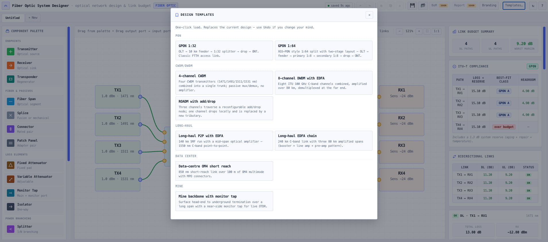
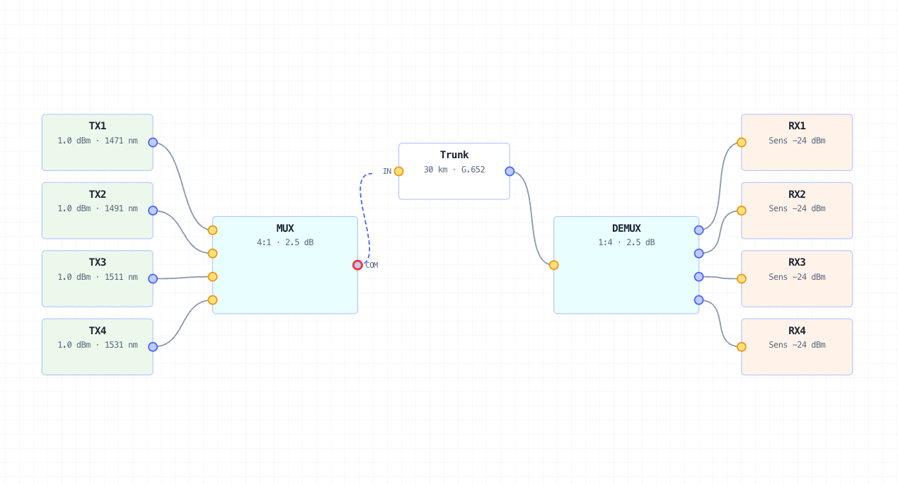
- Fibre Optic System Designer
Lay the whole link on the canvas, wire it port-to-port, and read the end-to-end budget and an OTDR trace from any node.
What this gets you
- A split ratio that serves every premises and still closes the budget
- Field losses in the budget, not a surprise at test
- A wired link the installer can build straight from
You walk away with: A PON access design with a sized split ratio, an optical budget that passes its class with margin, a line-by-line loss breakdown, and a wired link ready for the installer.
Commission a digital radio link
A digital link is only as good as the constellation it lands. You want a modulation that hits the throughput target, then proof the received signal is clean enough to hold it. This chain takes the link from budget to a constellation you can sign off.

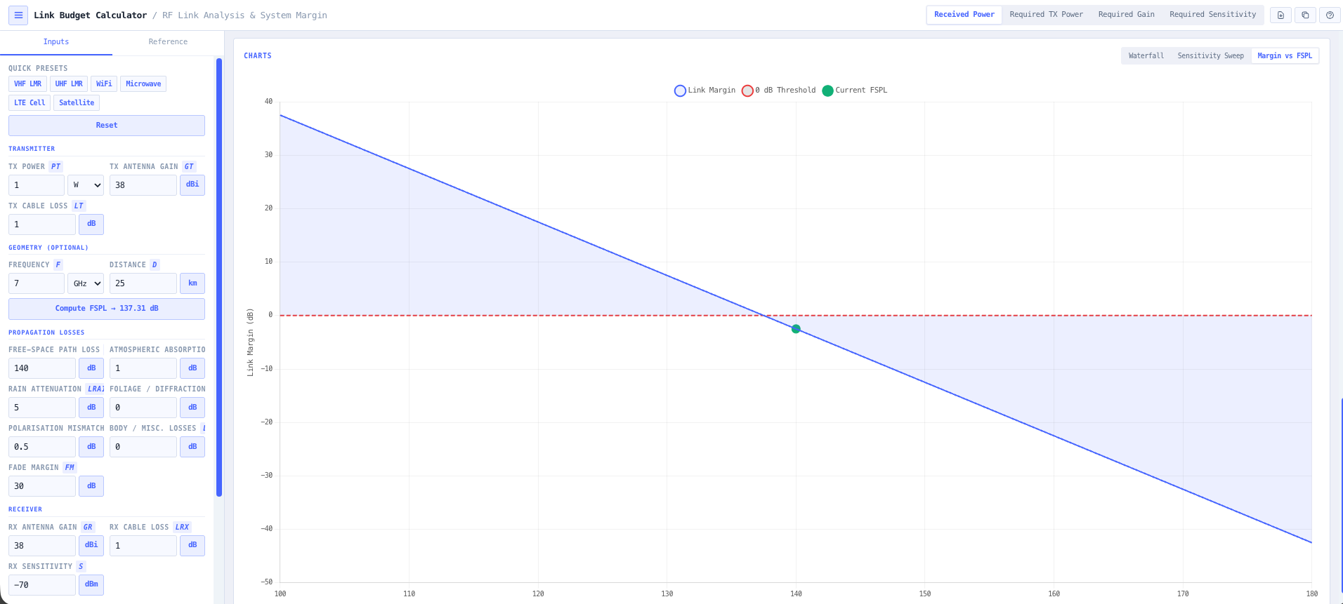
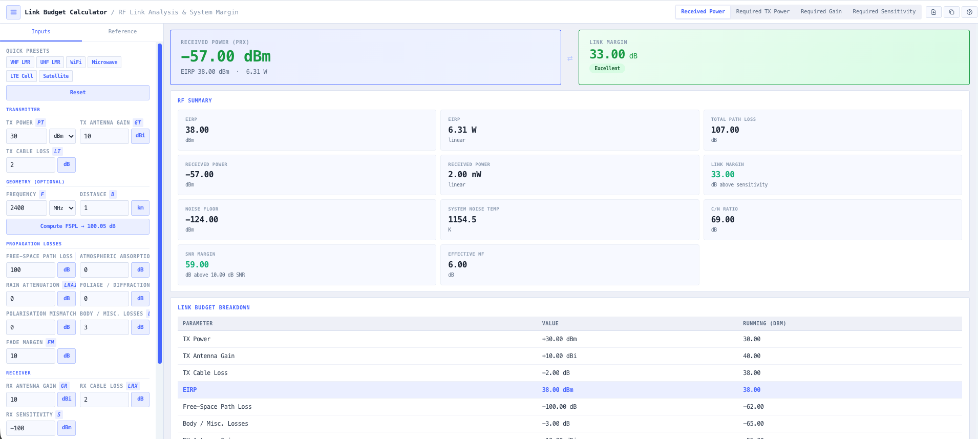
- Link Budget Calculator
Set the received signal level and the margin the modulation has to live inside.
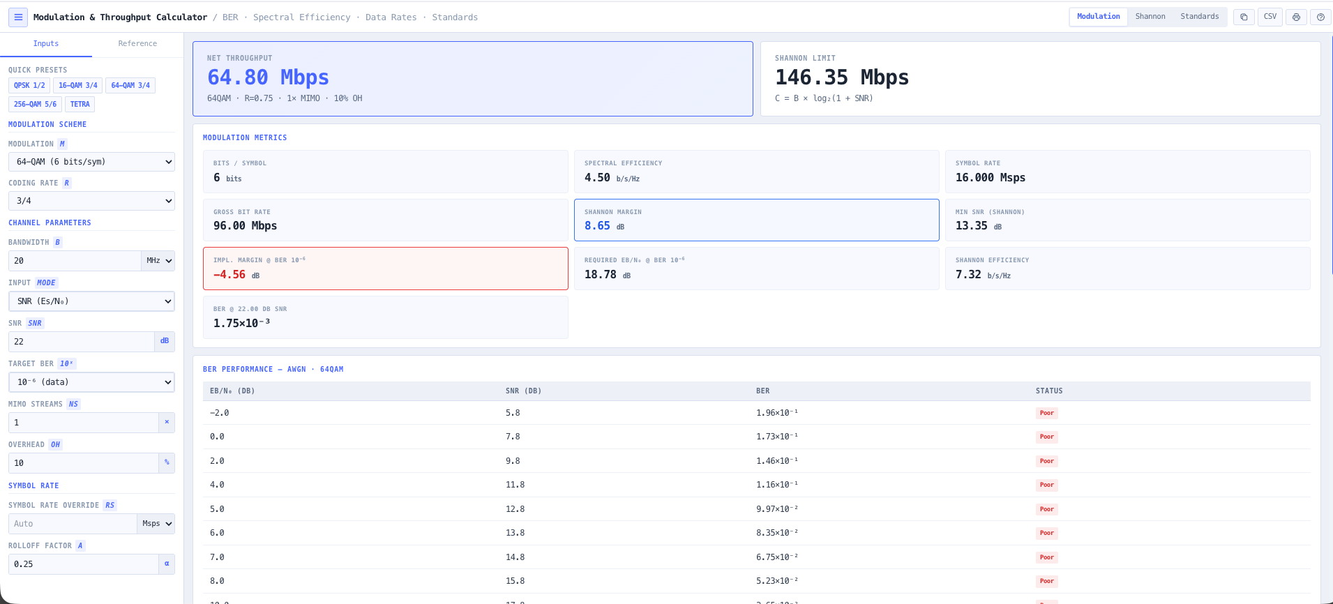
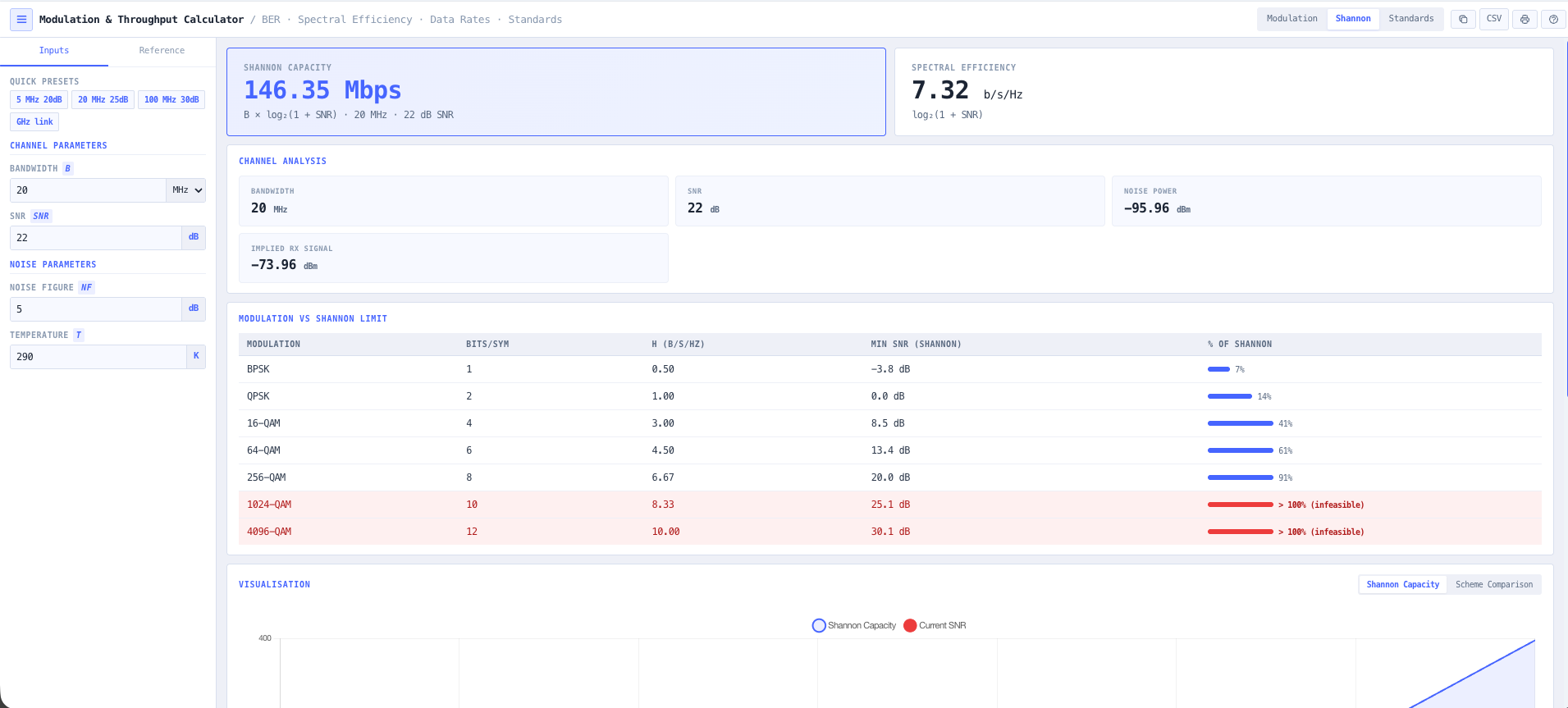
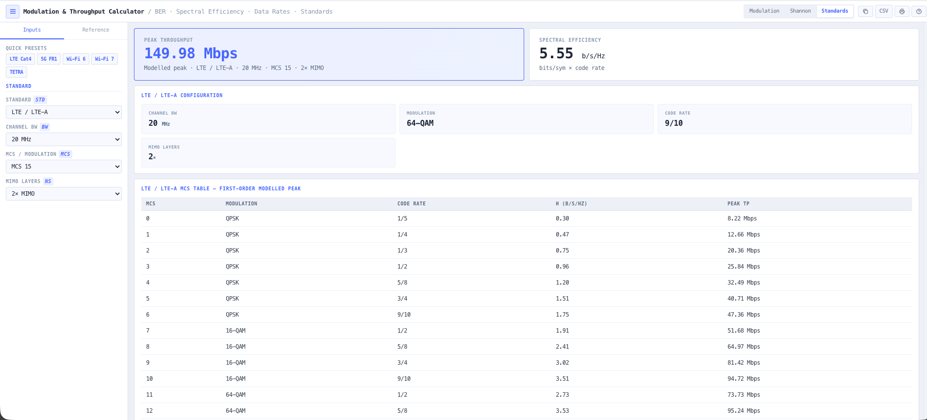
- Modulation & Throughput Calculator
Pick the modulation and coding that hits the throughput target for the margin you have.
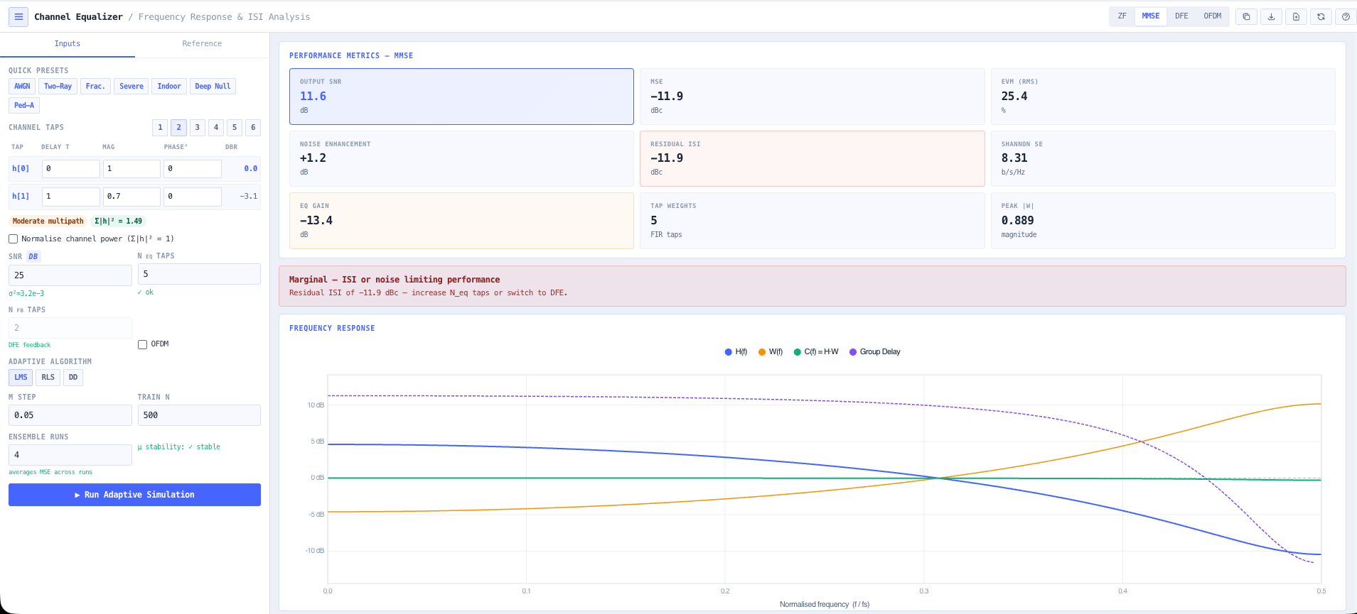
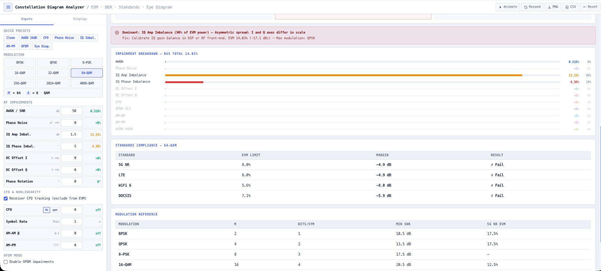
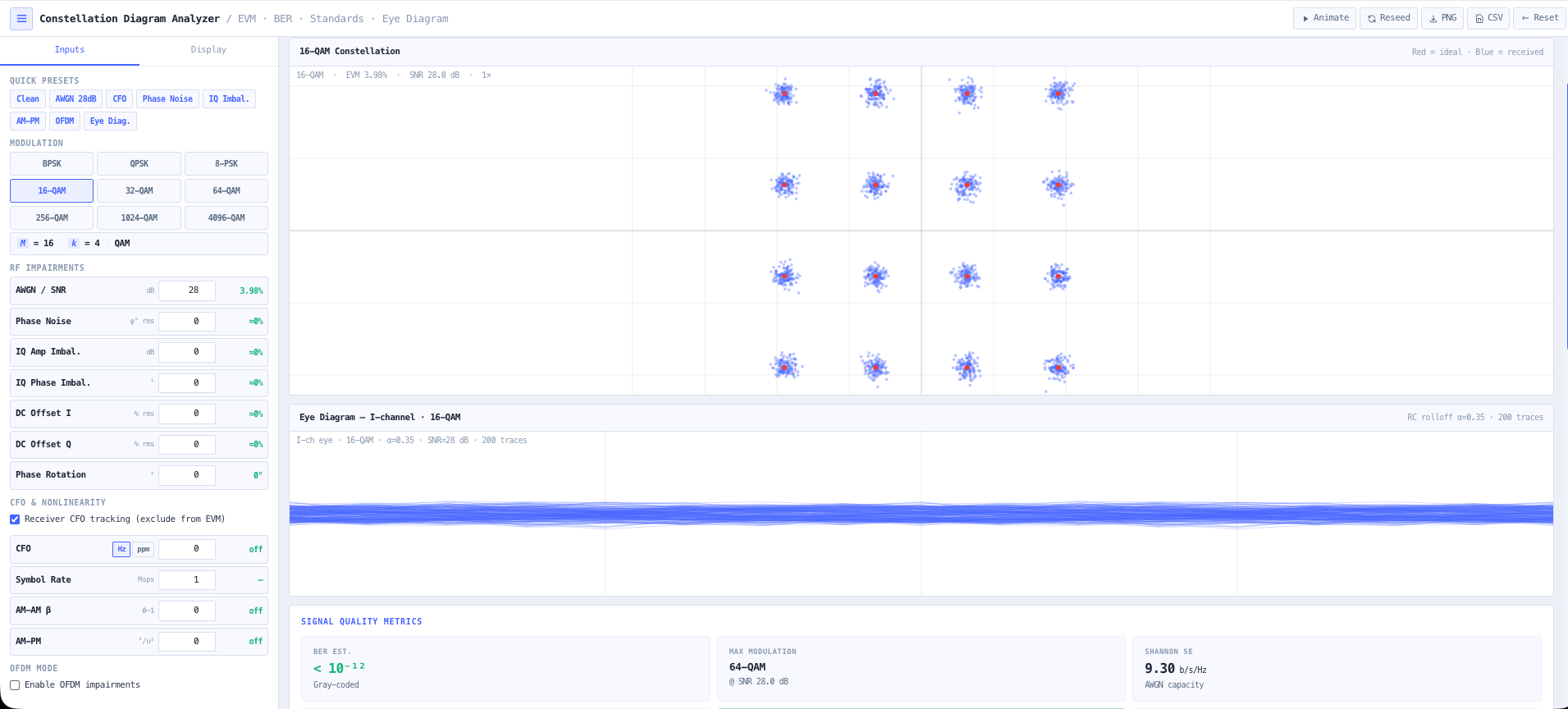
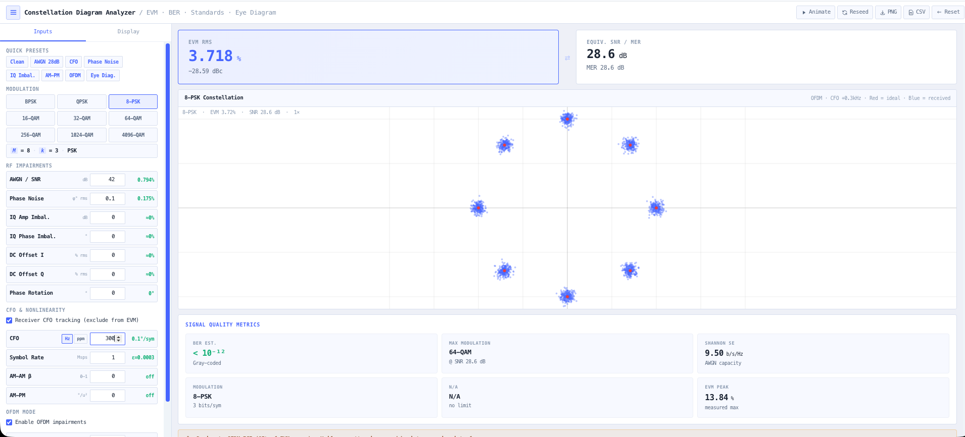
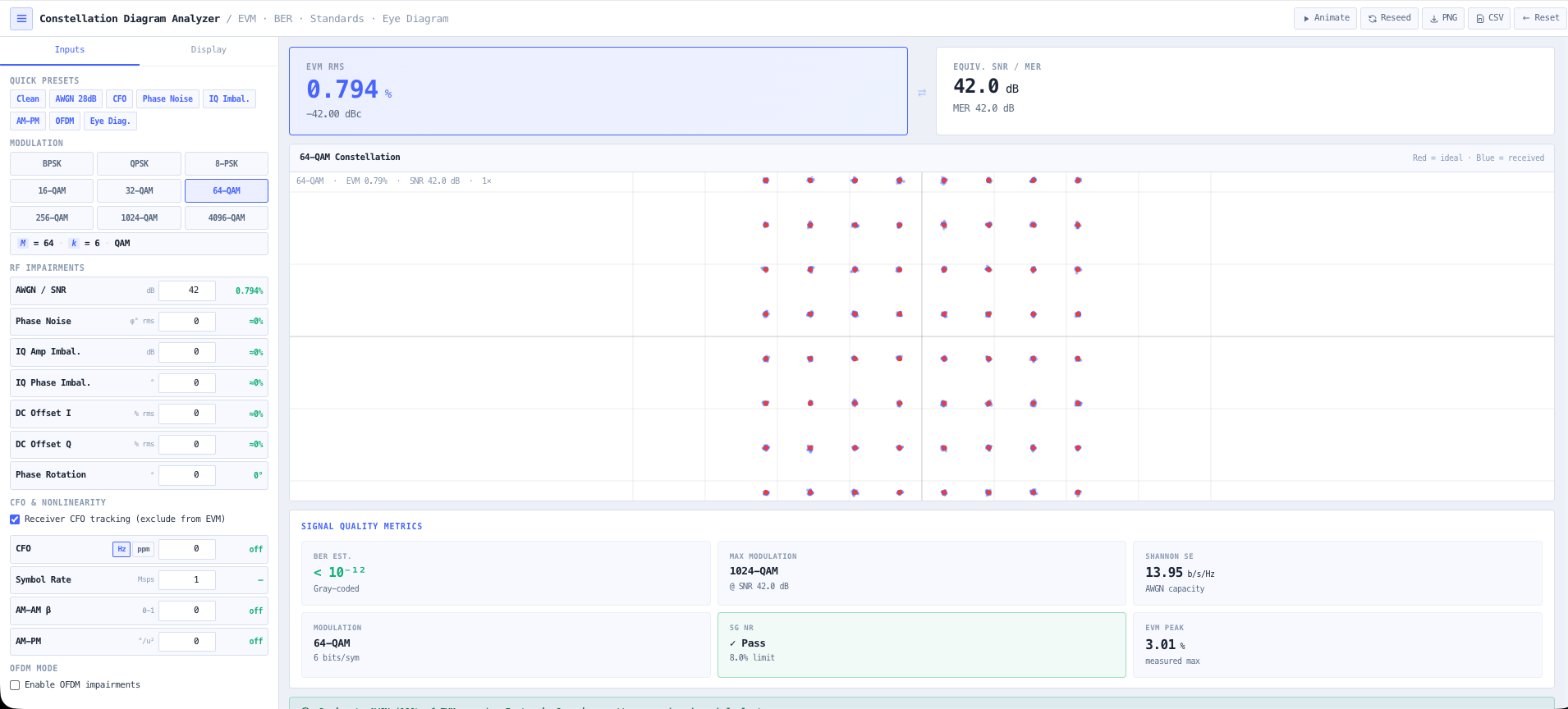
- Constellation Diagram Analyser
Plot the constellation and see how tightly the symbols land around their ideal points.
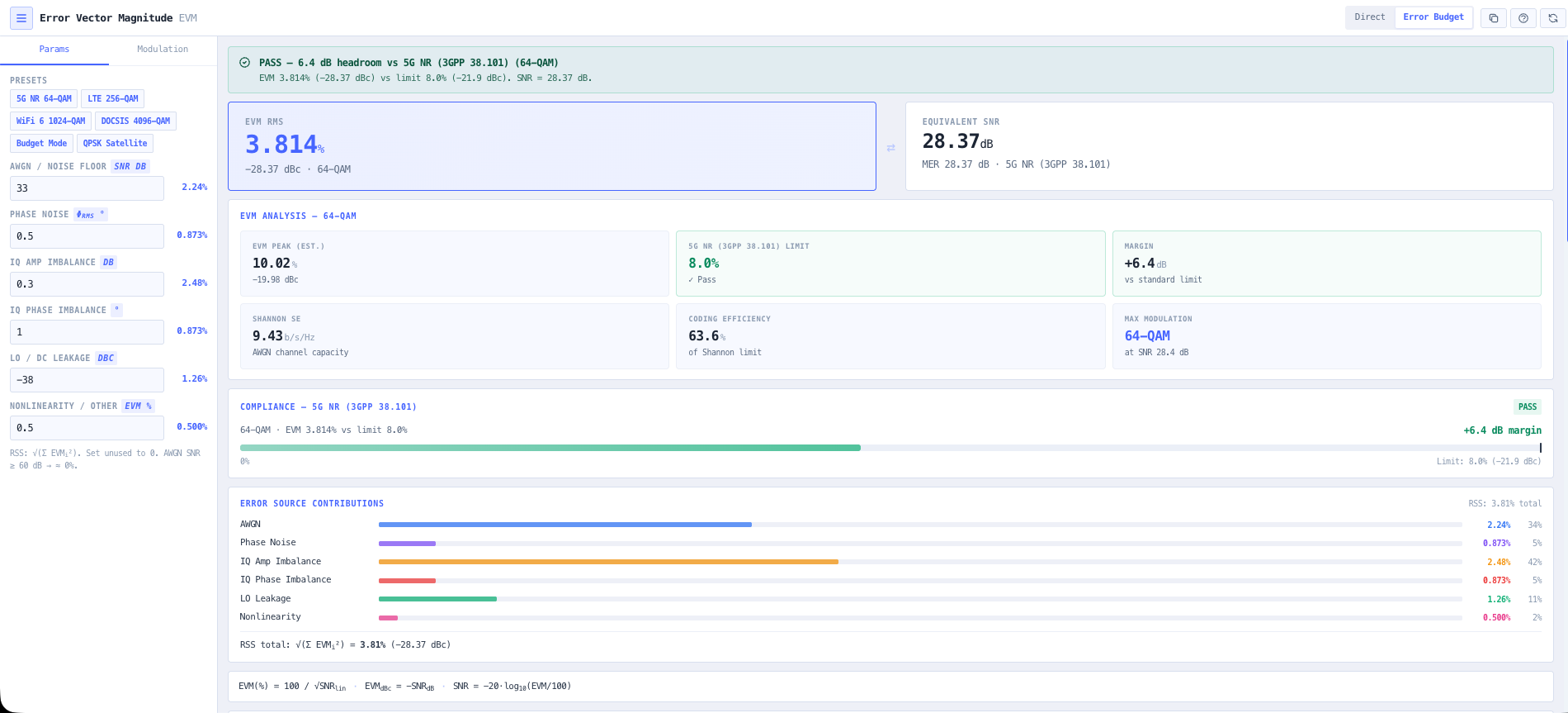
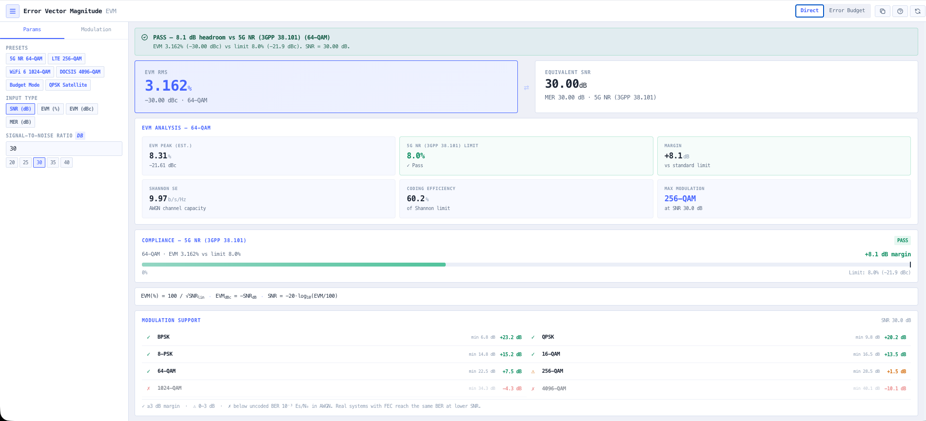
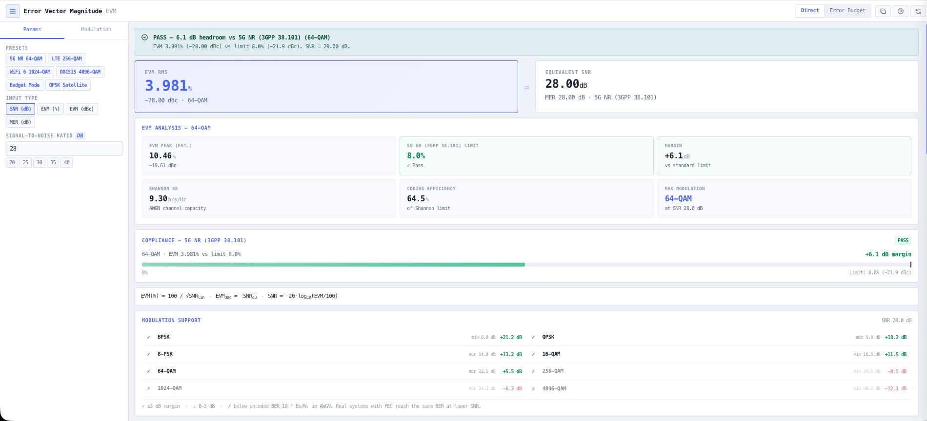
- Error Vector Magnitude Calculator
Put a number on the signal quality and check it against the limit for your modulation.
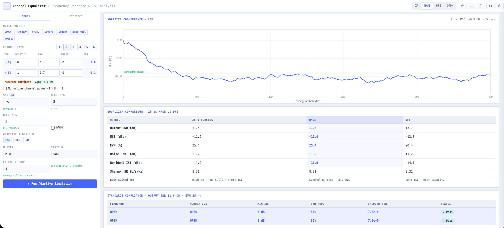
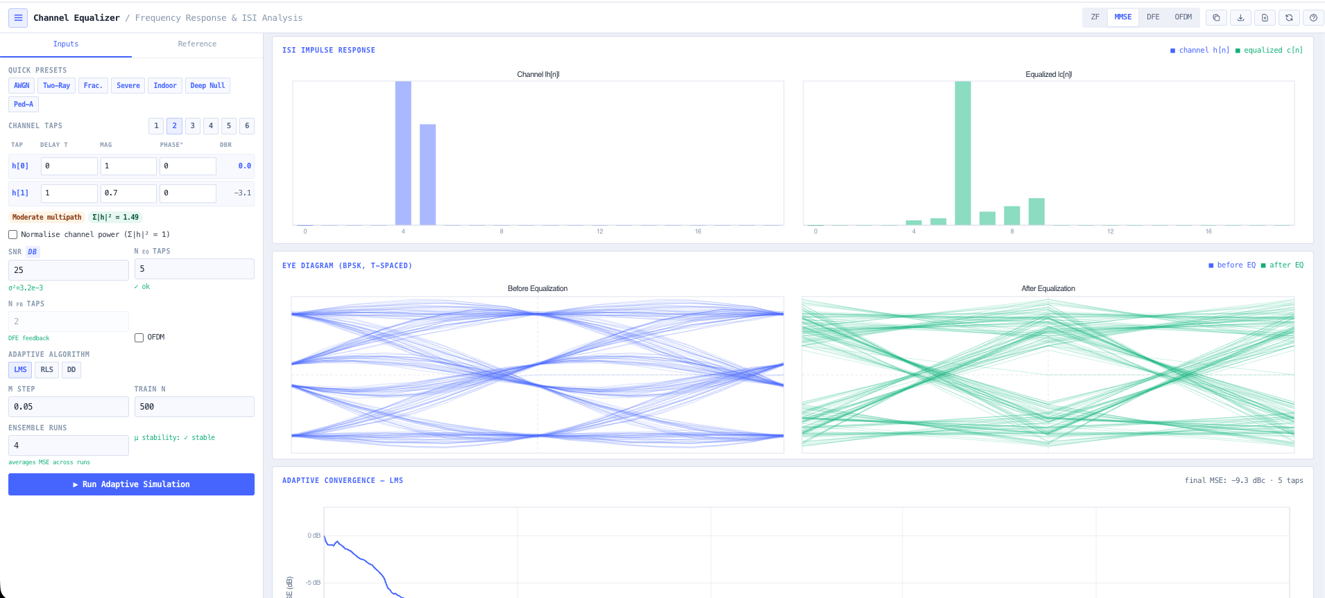
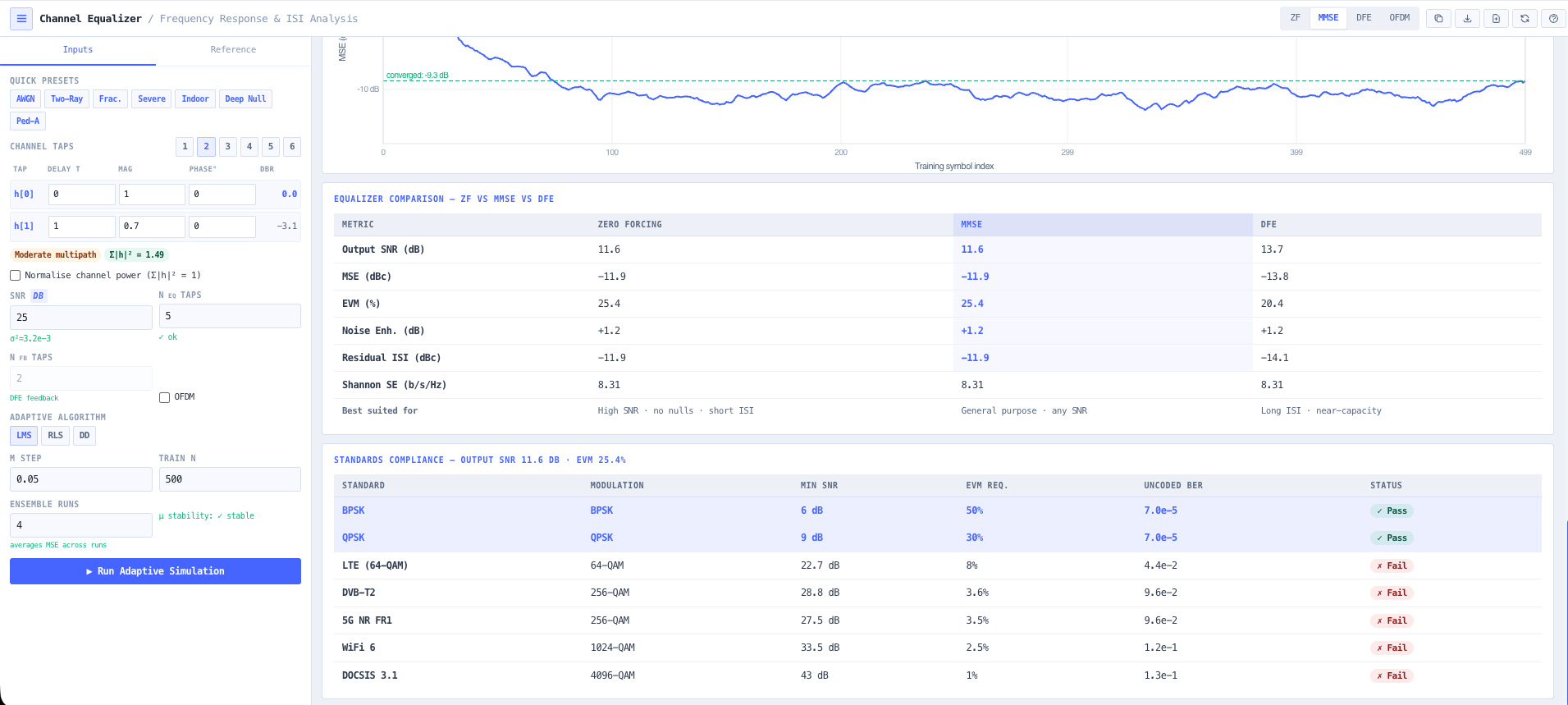
- Channel Equalisation Calculator
Equalise the channel to pull a smeared constellation back into spec.
What this gets you
- A modulation matched to the margin you actually have
- A throughput figure you can commit to, with evidence behind it
- Constellation and EVM proof the signal holds it
You walk away with: A digital link with a modulation matched to the budget, a throughput figure you can commit to, and constellation and EVM evidence that the signal holds it.
Why Design It Here
A platform you can audit, not a black box
The reason engineers reach for these tools on a real job: the working is visible, the data is real, and the outputs are something you can hand on.
The maths is shown
Every number is on screen. Open the working, change an input, watch it recompute. Nothing happens in a black box.
Anchored to real data
Models sit on top of real reference data, such as ACMA spectrum, terrain, and published cable and antenna specs, rather than invented constants.
Tools that chain
Outputs from one tool feed the next. The terrain profile you pull becomes the link budget becomes the fade margin.
Built for Australia
The regulatory environment, the standards, and the spectrum are Australian from the ground up, not a US tool with the units swapped.
Where It's Used
Designed for Australia's critical sectors
The same engineering rigour, from the underground to the boardroom. Each sector maps to a worked walkthrough above, so pick yours and jump straight to a scenario built like the job.
Pick a tool and start designing.
Most steps are live right now, with a few more tools on the way. Open the toolset and start designing, or see what a subscription unlocks.